
Brake lever set -BGM PRO Sport, adjustable + foldable- Vespa GTS
New levers for the Vespa - Instructions for changing the brake lever Vespa GT / GTS
News from BGM for the Vespa GT / GTS series:
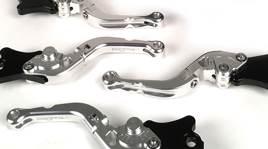
The BGM PRO brake lever for all Vespa GT, GTL, GTS models with a HengTong brake system.
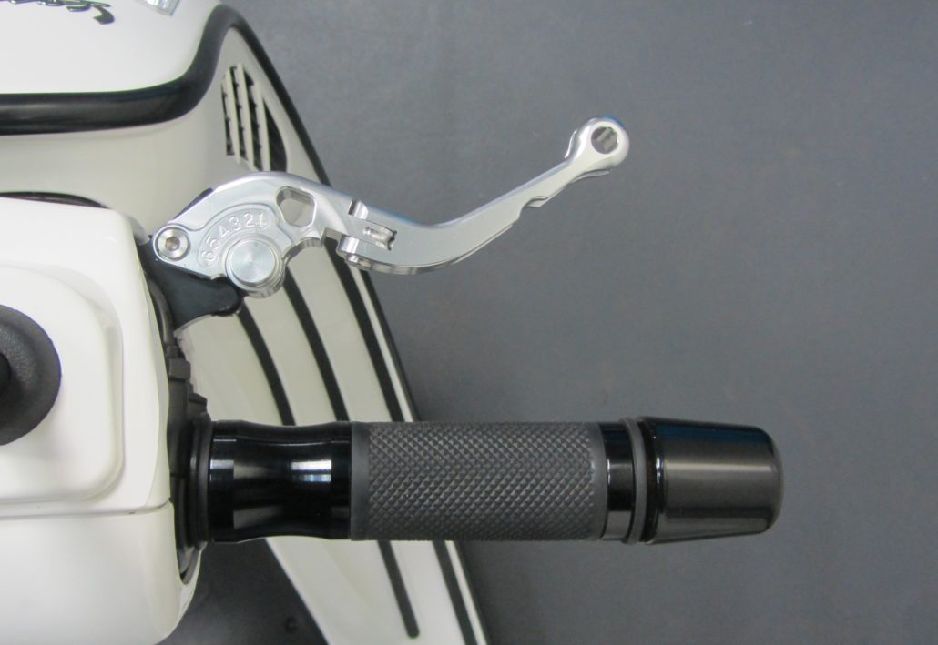
The CNC manufactured lever made of high-strength aluminum can be adjusted to 6 positions.
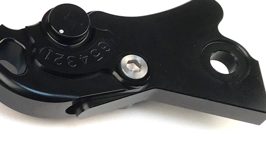
Using the discreet adjuster located on the underside of the lever, the actual lever can be adjusted to personal requirements at a distance from the handle and is therefore always perfectly positioned for safe actuation of the brake.
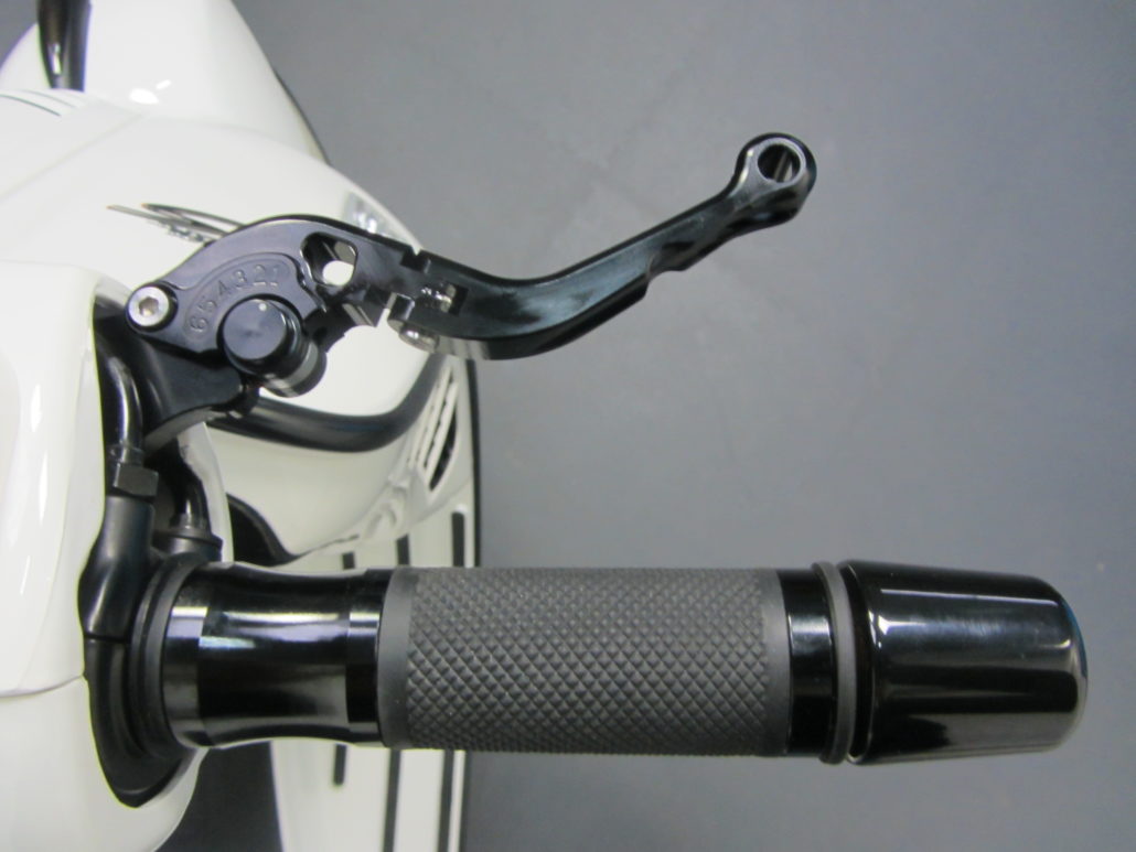
The lever is designed in two parts, foldable.
If the worst comes to the worst, the outer end of the lever can evade a sudden force from outside and does not break off.
When maneuvering in confined spaces in the garage, for example, the lever can simply evade resistance or be folded up and does not hook anywhere.
Here are brief assembly instructions for the Vespa brake levers:
You will need these tools:
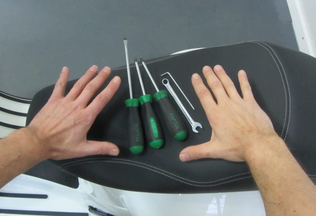
- Allen key 2,5mm
- Open-end wrench or socket wrench SW10
- Slotted screwdriver size. 2-3
- Slotted screwdriver size 5
- Internal multi-point wrench TX25
- Two hands, right and left, ideally with only one thumb on each side
- Open-end wrench SW17 (varies depending on the version of the mirror)
Preparation
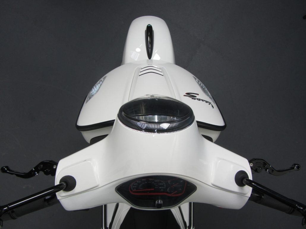
To have better access to the brake pumps, the front steering head cover is removed.
If a weatherproof glass adorns the vehicle, it must first be removed.
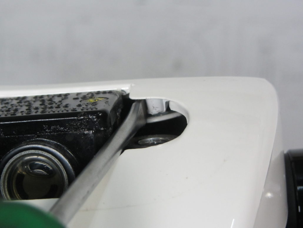
The rubber caps and the cover of the maintenance opening for the brake pumps hide the lock nuts for fastening the mirrors.
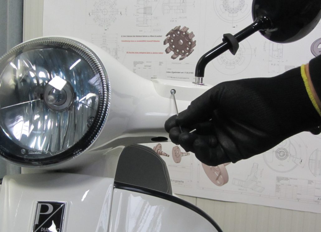
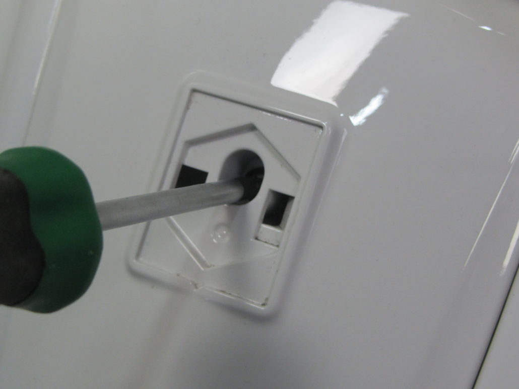
The screw of the cover of the maintenance opening is removed from the front with an Allen key 2,5mm.
After removing the cover towards the front / top, the lock nut of the mirror is freely accessible and can be loosened with a 17 mm open-ended spanner.
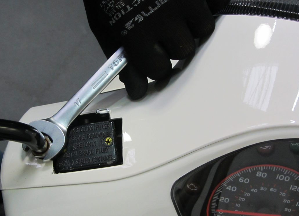
The mirror can then be screwed out to the left.
Both mirrors usually have normal, so-called right-hand threads. So turn to the right - tight; turn to the left -less.
In the lower area of the handlebar trim there are three screws, each from the right and left behind,
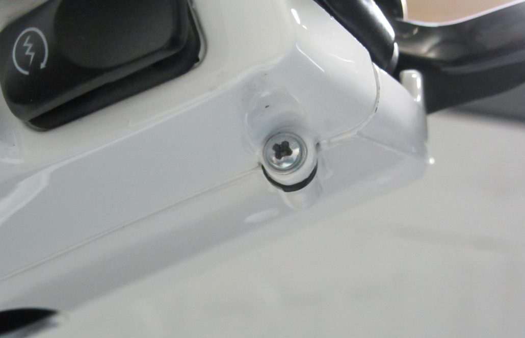
and are accessible in the middle from the front, below the headlight.
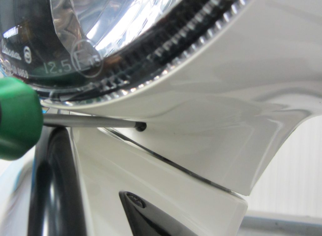
First all three screws are removed with a Phillips screwdriver PH2 and the securing clips are opened.
These plastic clips are not visible from the outside. The locks are accessible on the right and left via the maintenance opening of the brake system.
The clamp can be carefully unlocked with a slotted screwdriver.
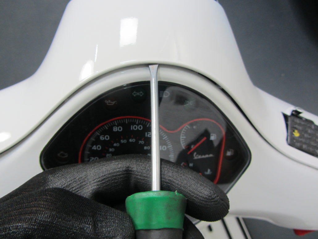
Another, hidden plastic fuse is located in the middle under the handlebar cover.
The snap lock can be carefully unlocked with a narrow slotted screwdriver.
The front steering head cover can be removed more easily when the cascade has been removed.
The casakde is only secured with an internal serrated screw (TX), hidden behind the Piaggio emblem.
The emblem has a small gap on the left-hand side in the direction of travel and can be lifted from there with a narrow screwdriver.
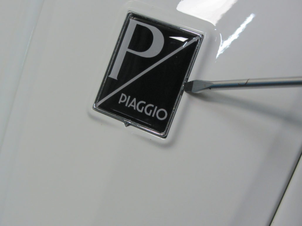
The only screw of the cascade is hidden underneath. This is loosened and removed with a TX25 key.
The cascade is removed upwards / towards the front. The front steering head cover, which is now already loose, can be pushed upwards a little through the cascade in order to release the safety hooks on the side of the cascade.
If the cascade is removed, the front handlebar cover can be removed in the forward / upward direction.
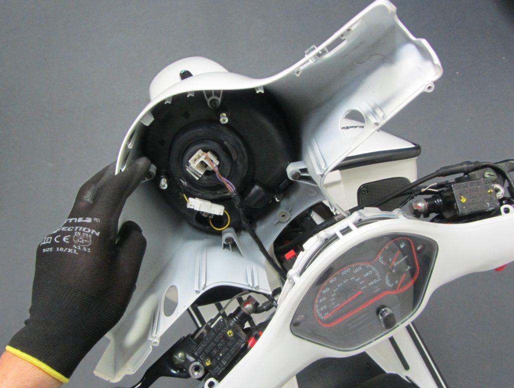
Loosen the electrical connections to the headlight and the panel is free.
Replace Vespa brake lever
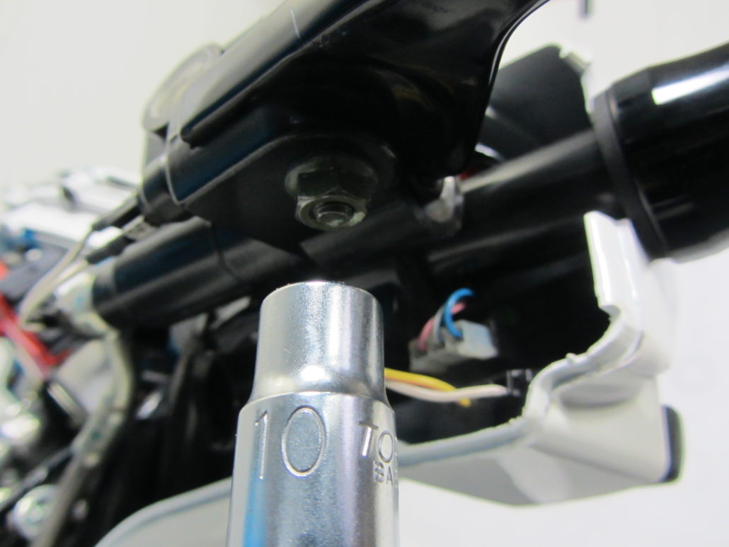
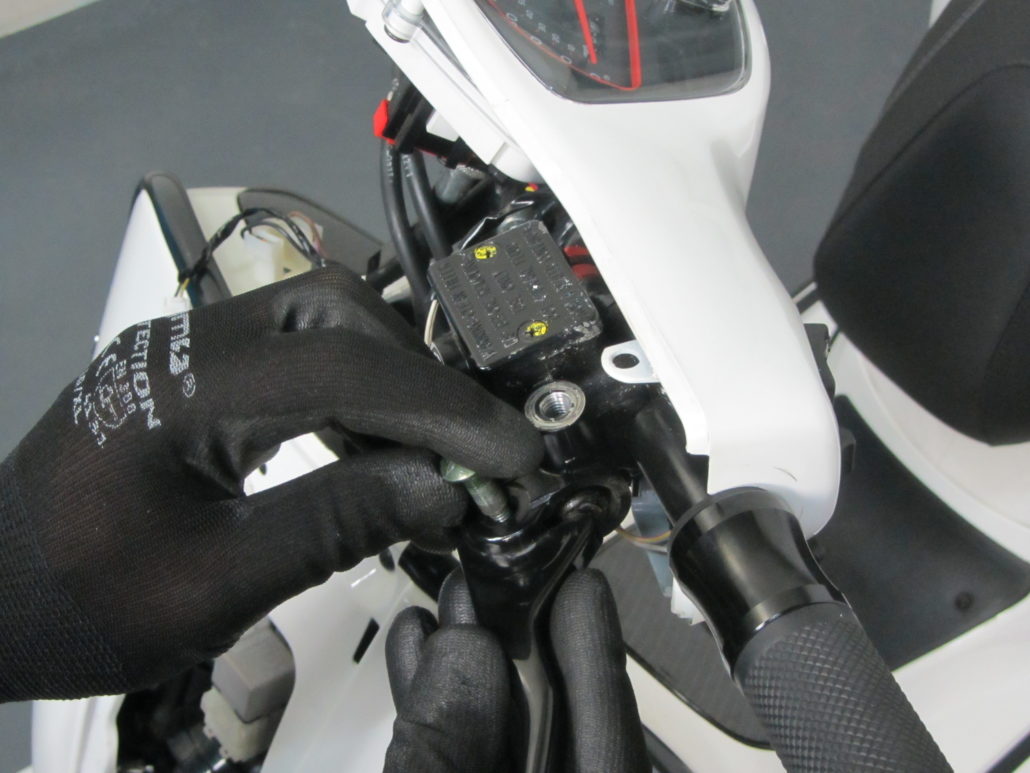
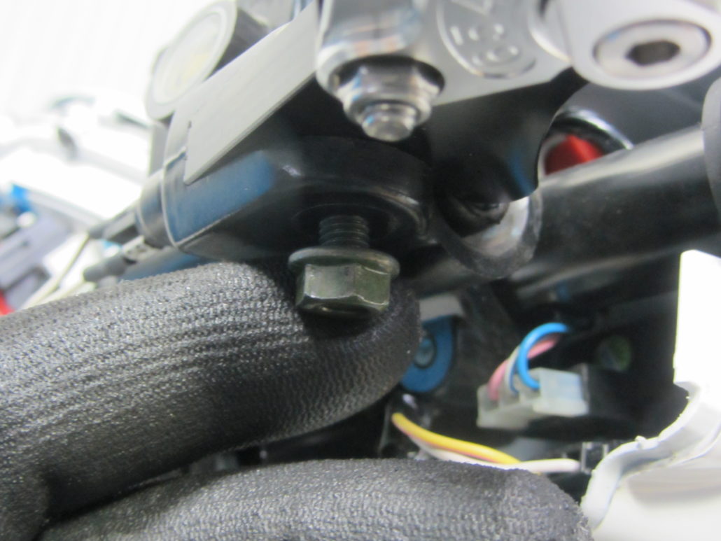
To dismantle the original brake lever, remove the lock nut under the brake lever holder with a 10 mm ring or socket wrench.
Then the bolt that supports the brake lever can be loosened with a wide flat screwdriver (min. S5.5).
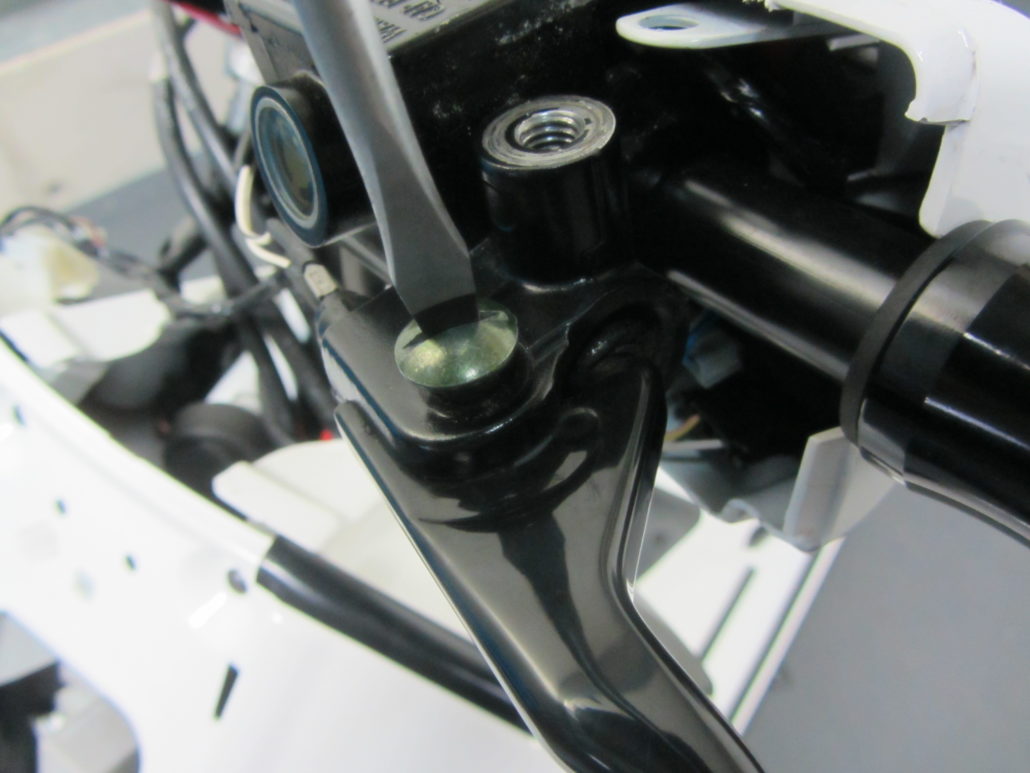
Carefully pull out the bolt while holding the brake lever.
To support the lever joint, two sliding supports, in effect washers, are inserted into the lever.
When removing the lever, be careful not to lose the washers.
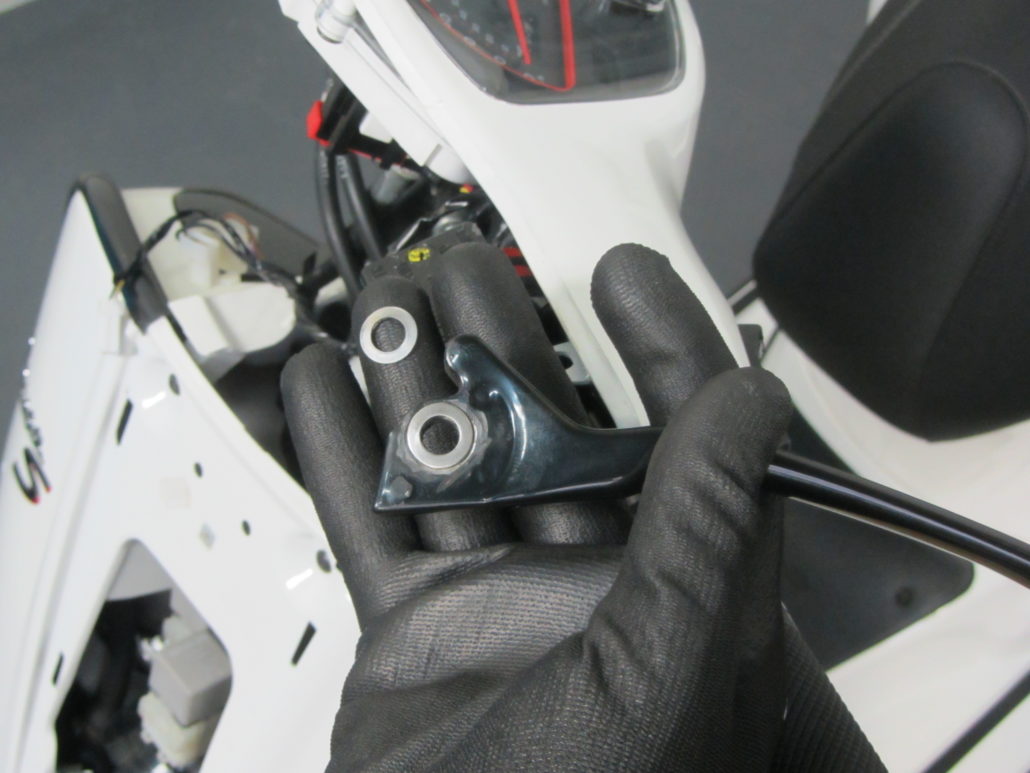
The sliding pads are required again for the BGM PRO brake lever.
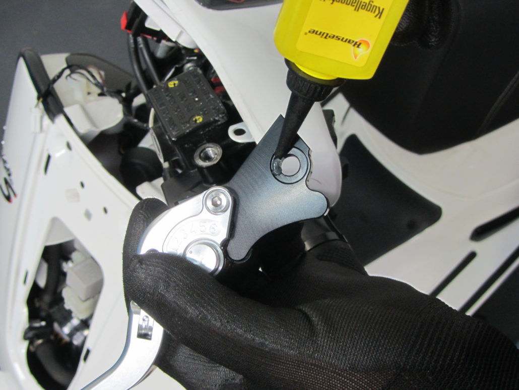
In order to make the assembly a little easier and so that the lever joint can work noiselessly and with little wear,
the washers are glued to the lever with a little grease and thus held in position during assembly.
On the right-hand side of the handlebar, the lower throttle cable can simply be spread apart for assembly so that the lock nut is freely accessible.
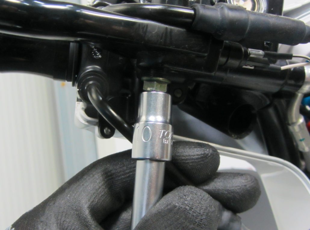
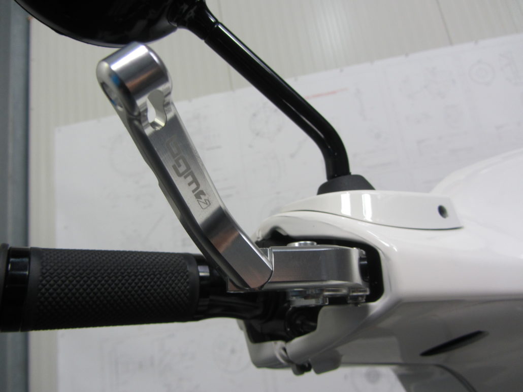
After inserting the lever, screw the guide pin back in and secure it with the lock nut.
Then reconnect the headlight and fasten the handlebar trim again with the three screws, starting with the plastic clips, mount the mirror - done.


Leave a Reply
Want to join the discussion?Feel free to Contribute!