Scooter Center Italy

With Vespa and Lambretta to the promised scooter land

We love Italy and are back in Bella Italia right now. Italy is of course the country of origin of Vespa and Lambretta.

VW bus with Vespa and Lambretta in Italy-sc

And how could it be otherwise: the way it is for you real Scooter shop should belong here, on Lake Garda in Italy, over 23 years ago history of Scooter Centers began.

Malcesine vespa lambretta italy-sc

In Malcesine in the middle of wonderful olive groves, on the east bank of Lake Garda, Oliver Kluger had the very first scooter (a Vespa Rally TS 125) for the Scooter Center bought and later sold to "Mod-Volker" from Cologne. Volker drives this wonderful Vespa still today, he is our very first customer and of course has remained loyal to us to this day.

vespa Primavera ET3 Italy

Scooter Center - Spare parts accessories and tuning parts for scooters

Even if we focus more on that today Spare parts, accessories and tuning parts for scooters focus: even today we still have used Vespas on offer.

Scooter Center Italy

Used Vespa

We just got a big shipment used Vespa scooter to get. We first have to get an overview.

Here we will keep you up to date. Info about used Vespas


This time two superlative missions take us to Italy:

  1. The ugliest Lambretta in the universe
  2. The most beautiful Vespa in the world


dean orton lambretta scooter center

Bon voyage - Dean visits this Scooter Center with the BSG Corse Lambretta

Dean Orton, the founder of Rimini Lambretta Center visited us in Scooter Center. On his way from Rimini via the Venlo Scooter Run to the ESC race at the Harz Ring, he stopped by for a few days. Dean use the trip to the BSG Corse engine to test its suitability for everyday use and travel. In doing so, it was anything but sparing the engine.

BSG Corse Lambretta test drive

dean orton lambretta

The test drive should be as real as possible, so Dean just packed his mod stuff and also:

  • another exhaust to test
  • all sorts of tools just in case
  • Camping equipment
  • and what else mod needs

Then he chased the Lambretta through the streets. From Rimini in Italy over the Alps to Austria and over Germany to Venlo in Holland. The way home then takes him back via Germany, past us and then on to the ESC race at the Harzring.

130km / h cruising speed with reduced 50PS

He reels this distance relatively relaxed at a constant cruising speed of 130km / h. And that with sufficient reserves to be able to overtake at 150km / h. Considerable when you consider the very short gear ratio of only 4,9. With this powerful motor, other speeds can also be achieved.

The CNC manufactured 305cc cylinder is throttled to approx. 50PS via the programmable ignition. Unthrottled, the engine already produced 63PS on the dynamometer at the Rimini Lambretta Center.

ESC roller race on the Harz-Ring

A European Scooter Challenge race will take place on the Harz-Ring this weekend. Dean meets the Casa Lambretta Racing Team here. The first tests and preparations for the race will take place on Friday. The Casa Lambretta racing scooters are equipped with the new parts of the Casa Lambretta Performance parts and some bgm PRO parts. We have the Casa team with the complete bgm PRO Lambretta chassis, the bgm PRO Lambretta silent blocks and the bgm PRO Superstrong Lambretta clutch equipped.

Our first time!

Even if we've known each other for ages and that Scooter Center Just as the Rimini Lambretta Center was founded around the same time, we already met at various events across Europe, but this year we managed to visit each other for the first time.

dean orton lambretta dean orton lambretta

In April we went to the Open Day and had a great time there in this brilliant Lambretta shop with our Italian friends, great Italian food and of course many great and unique legendary Lambretta models such as the Lambretta two-cylinder prototype and the BSG 305 Lambretta.

Here is the video from the Corso, Philipp on the BSG Lambretta

On Monday So it was finally time, it was an honor for us Dean im Scooter Center to welcome. We loved every second and there were lots of stories old and new to share and it was very fun. After a few “business talks” we had dinner together and it got very late. Dean praises ours Scooter Center Generation XI Smallframe Vespa the most beautiful object in the universe - just one breath later our bgm demonstrator Lambretta than that ugliest Lambretta in the world to brand. Mhhhh…. Since we were already confronted with this opinion at the Riva del Garda Customshow 2013, there had to be some truth to it. So we had to do something about it. So we decided to make the Lambretta available to him and to adapt the optics to the perfect mechanics.

dean orton on a lambretta
Tuesday Dean tests the Lambretta on the streets of the beautiful Rhineland and came right on time for the traditional afternoon tea to discuss some new Lambretta products.

On Thursday Dean actually wanted to look at our order process. Unfortunately, we got the glorious idea to test his scooter and both exhaust systems on the test bench. The diagrams of our P4 dynamometer almost coincide with the diagrams driven in Rimini. Time flew by and after dinner Dean was already on the way to the Harz-Ring.

Many greetings to the entire Rimini Lambretta Center team and to Vittorio with his Casa Lambretta Racing Team - we keep our fingers crossed for the race

Generation X Custom Vespa

Vespa Custom GENERATION XI is celebrating its birthday

This month our celebrates Shop demonstrator Date of birth. The GENERATION XI was created for our twentieth birthday. In the meantime, the Vespa Primavera ET3 - in its second life - is already 2 years old! How the time flies…

Generation X Custom Vespa

Experience custom scooters live:

Come visit us and celebrate with us. We will soon be here with Generation XI, for example:

  • Scooterist Meltdown 7-9.2.2014
    All inclusive weekender. Pay once, enjoy everything for free ...
    http://www.scooterist-meltdown.de
  • Scootershow 22.03.2014
    The Scooter Customshow, international exhibitors and visitors, admission only 5 euros
    www.scootershow.de

custom vespa primavera generation_x

Small but OHO!

Only 2 years old and already a fully grown custom scooter! Because our GENERATION XI will no longer grow: the size depends on the design - it's a Vespa Smallframe (Vespa Primavera ET3) and they are just a bit smaller ;-)

But appearances are deceptive - actually it is Scooter Center Shop demonstrator a really big one. In this case both outer and inner values ​​count, but see for yourself:

Vepa PRIMAVERA

Vespa Custom GENERATION X bgm chassis with TÜV Vespa Custom GENERATION X bgm chassis Vespa Custom GENERATION X steering Vespa Custom GENERATION X seat Vespa Custom GENERATION X engine

On Sunday we were at the custom show in Antwerp. With a clear blue sky and spring-like temperatures, the mood among all visitors, exhibitors and the organizers was excellent.

We have a lot of ours at our stand Vespa catalogs distributed, new bgm We presented parts and prototypes and we were happy to see what kind of customers we have.

The scooters on display were a class cut through the various categories. From the PK with leopard bench pimped up with accessories to fantastic original paint conditions and complete customs from the island. The parts market has again found a number of bargains in itself. Our demonstrator has cleared three trophies: BEST VESPA CUSTOM, BEST ENGINEERING and PUNTERS CHOICE. The fact that we had the audience's favorite on the show with PUNTER CHOICE was the i point of an all-round successful and beautiful day.

Thanks to the LCD for temporary stand takeover and the tip with the Friture! And of course to the organizers! We'll definitely be back next year!

[Nggallery id = 10]

We don't want to withhold that from you! The first test run of the 130 Polini EVO engine. The motor is still in the motor holder and equipped with jet nozzles!
Many thanks to Thomas the Second, who edited the video for us in his spare time. Thomas will soon be joining us at the Scooter Center begin. We are looking forward to it!

Next weekend we're going with ours SCK shop demonstrator on tour. The 13th international custom show in Antwerp is on Sunday. We will of course have a stand again!

We look forward to it!

Unfortunately, the last days before the custom show in Ried were a bit hectic, so there was no time to maintain the blog.

Nevertheless, we do not want to withhold the last steps and pictures from you.

The motor is temporarily hooked into the frame to test whether everything fits and there is no pinching.

Of course, not everything fits the first time you try it on. Why also?

No seriously. The frame must be adapted to the Falc intake manifold because the shape of this must be shaped in such a way that the carburetor does not hit the frame in any driving situation.

Here it is enough to remove a few mm so that the Falc socket fits.

The 38 Airstriker is being converted to a cable choke.

The CDI of the ignition also needs a place. The retaining plate is intended for conversion to V50 and Primavera engines, so a second hole must be supported and countersunk.

In the SmallframeThere's a real shortage of space for the CDI at this point, which is why the retaining plate, which is vibration-dampened in Piaggio rubbers, has a special perforation so that nothing is offensive even when it is fully compressed.

Here is the "wedding picture"

Now the adjustment of the steering tube still follows.
As a result of the conversion, the top of the steering tube must be shortened and the undercut for the clamping screw of the handlebar must be moved.

So the old undercut must first be welded shut and then a new one must be filed in the correct position.

The handlebar can be mounted.
A PK-XL rocker arm is used with our engine. In connection with a V50 and ET3 standard rocker switch in the handlebar, however, this results in too long a shift travel.

That's why we use a PK-XL pulley to keep the shift travel short and crisp.

And here, too, the devil lurks in the details:

Compared to a V50 / ET3 rocker switch, the PK pulley is oriented a little further towards the end of the handle. As a result, the shift cables would now run at an angle between the cable stop in the handlebar and the pulley, which increases the wear on the cables and leads to poor switching behavior.

So it is necessary to lengthen the switching tube by a few mm so that the pulley and cable stop are in alignment again.

The connection point for the planned extension of the switching tube is deliberately set as far inwards as possible, otherwise, if one only had a steel ring a few mm long, there could be problems with welding.

With the extended shift tube, the roller and stop are again in alignment and the shift cables are now straight.

On the gas pipe side, we also have to come up with something.

A conventional quick throttle grip is out of the question for our classic racer for optical reasons.
It would also be possible to use a pulley. The size would be enough to fully open the 38 Keihin.

A herd of 29 horses, however, needs to be led with a gentle hand and so the linear opening path of an exactly round roller is not possible.

A progressive gas roller, on the other hand, has the advantage that the carburetor is opened slowly at first and faster as the slide stroke increases. This effect clearly takes the nervous behavior out of the resonance range.

Pay attention to the track for the throttle cable in the picture below. If you look closely you will recognize the eccentric course ...

Since we manufacture the throttle pulley ourselves, the dimensions are determined accordingly so that the throttle cable runs straight from the cable stop to the pulley.

The orientations of the holes for the clamp and the screw nipple are then fixed in the handlebar.

A screw simply serves as a stop for the roller. Adhesives are used to prevent it from coming loose.

Finally comes the tank, here with a Fastflow fuel tap with reserve indicator.

It takes a little getting used to, however, that the Fastflow valve has swapped the reserve and closed positions.

Finally, a SCK-Ancillotti has just been installed and then our floor is ready.

Cleaning is only done at the CS in Ried.

Out of more than 120 scooters, the most beautiful scooters were awarded in 17 categories.

A great success for us, the SCK-Racer Generation XI is “BEST SMALLFRAME"

In the last second our racer for the CS was ready here in Ried.

On Friday morning we did the last few things
After a 6-hour drive, you arrive at the Ried trade fair center - quickly unload, assemble and clean the floor.


You can find more pictures at here on FB ...


That had to work too!

... because whoever looks back on a successful 20-year existence this year ...

Exactly this morning at 10:00 our frame comes rolled into the yard - finally!

Everyone is excited to see what the good piece looks like, so first unpack and admire!

Unfortunately there is not too much time to look at every detail in peace, because the CS in Ried is approaching with great strides and time is of the essence.

So the step rails are attached directly - we use hammer rivets for this, as it should be.

The rivets are attached with a hammer drone. The waffle pattern creates the typical Piaggio character.

We had the strips and end pieces coated with black powder, because in the short time nobody was to be found who could "just" provide the same with a beautiful gold plating.

In my opinion, a very successful stopgap solution.

After moving in the bearings followed by the harness and the Bouwdenzug.

Last but not least, we get the engine from the P4 and install the rear disc brake system, which had to give way to the brake cable actuated drum for the test stand due to time constraints.

Our racer is cuddled up carefully - lights off - good night and see you tomorrow.

The engine for our racer is being put to the test today.

For settings and a performance measurement, we mount the motor on a work stand.

As seen above, we first check the ignition timing. With a stroboscopic lamp you can see whether the markings are correctly aligned with one another.

The picture above is at 2500rpm-1 emerged, this speed should be observed at least when checking the ignition markings, as the Ignition curve of Vespatronic above and below this speed already runs into the adjustment range.

Here on the assembly stand.

We equip the “throw nozzle” 38 Keihin Airstriker with the following Share:

Idle jet 52

DDJ needle, 3rd clip from the top

Main jet 165

After checking whether everything couples and shifts as it should and after warming up, this diagram results.

Already quite good for the first attempt with throwing nozzles.

29.1PS / 24.4Nm and a band with more than 20PS over almost 3000rpm-1 are a nice start. We'll do more tests and maybe we'll find one or the other horse.

With the certainty that our engine is working, we are eagerly awaiting the arrival of frames and attachments from Austria tomorrow.

At Pfeil Design in Austria, we are working hard on our racer so that the frame and all attachments are with us on Tuesday.
Then you have to go full throttle for 2 days so that the bullet is ready in time for the custom show in Ried and you can see it on site.
In the meantime we are making the final preparations so that the engine may go to the test bench on Monday :-)
So let's start with the last little things ...
The Grand Sport oil drain plugs are equipped with a magnet, which holds the resulting metallic abrasion, which reduces wear.
Unfortunately, there are no bores on the engine housing for the wire securing of the oil screws, which is mandatory on race tracks. In order to get a visually pleasing solution, Dennis makes a small retaining plate “just quickly”.

Quickly twirl the wire on it ...

If screws are secured with wire, one should always make sure that the wire is guided around the screw in such a way that the screw always has to "pull" on the wire if it wanted to loosen and the direction of pull of the safety wire does not favor loosening the screw.

Other important little things are added ...

Kickstarter and the bracket for the Clutch.

Here, too, something has to be reworked ...

Our engine also has to be ventilated, unfortunately the really large carburettors were sold out, so we are content with one Keihin, 38 Airstriker.

The Falc intake manifold that we use comes with its stuffer. The Polini seal for the membrane must therefore be adapted.

Fortunately, Polini supplies a suitable Falc stencil directly :-)

At the bottom left in the picture you can see the foot of the camera tripod.
That happens when the “photo studio” is actually the welding table ...

... further in the text.

Seal fits, mount suction.

Now that the suction device is installed, let's turn to the cylinder hood.

Direct suction, air-cooled Smallframe Cylinders have the disadvantage that the hot air flow is directed through the shape of the original cylinder hood directly onto the intake manifold.

This has 2 main effects:

1. The suction device becomes disproportionately warm, which in turn reduces its performance.

2. The hot air is blocked by the intake manifold, which can cause thermal problems.

So we have to edit the cylinder hood accordingly to ensure that the intake port remains as cool as possible and that the cooling air is still safely discharged.

The hood is first roughly trimmed and then brought back into shape with a heat gun. The hood has to be adapted to the cylinder again and again.

As soon as the shape fits, the holes for the cooling air are made.

When milling you should make absolutely sure that the milling cutter does not get too hot. Because the plastic cannot absorb the heat generated to the same extent as metal.

This is how it should work.

The last little thing for today is the cable box.

The new bgm fumesr are installed on a trial basis.

The V50 and Primavera / ET3 models have the rear shock absorbers very flat and there is a risk that the lower spring base will come into contact with the motor housing.

That's why we made an angled shock absorber fork especially for this case.

This ensures that the shock absorber can work without contact.

The one comes just in time “Big Bertha” exhaust from Ludwig and Scherer.

Because the racing exhaust systems are usually delivered oiled, our Bertha still has to go with them Brake cleaner must be degreased before you put your little black off heat-resistant exhaust paint slipped over.

So slowly we can start to complete the engine.

A real advantage is the removable traverse, which is quite easy to use when pressing in the truss rubbers.

The special, 70shore hard truss rubbers were made by Robert from our racing team.

The rear wheel hub and brake caliper mount are also back from the galvanization. Now we can try whether everything on the engine fits together.

Here with the test rim ...

Completing the engine is on the agenda for tomorrow ...

Before we continue with the ignition as promised today, there is first good news from Austria and on the subject of shock absorbers.

Finally the dampers for our project have arrived, of course changed visually to match our racer compared to the later series.

At the “Pfeili” work continues ...

But it is much better that the finished frame should be with us by Tuesday next week.

That would mean a full 2 ​​days (we want to leave on Friday at 6:00 am!) For the assembly.

Now the ignition continues.

The base plate is screwed onto the motor housing in the Vespatronic basic setting.

Then we put the pole wheel on.

It is characteristic of Vespatronic that the normal Vespa flywheel nut can usually only be fitted with a nut that is turned off in diameter.

Or you can use a mother from the Piaggio automatic range.
Within the Vario nut for the large Piaggio engines, the wrench size is reduced to 18 mm.
In addition, the nut comes directly with the fuse pressed on.

A nut SW18 fits unchanged into the Vespatronic pole wheel.

The pole wheel is tightened to 65Nm.

In order to check the ignition timing later and to make understandable changes, we still have to attach ignition markings.

We use the reversal measurement for this.
We apply the first marking with a piston stopper, which is to serve as a defined stop.

Mark 1

then over the UT again to the stop. Here you transfer the marking from the pole wheel back to the motor housing.

The OT is between these two markings, the easiest way to mark it with a compass.

Now that we know the OT, the desired ignition markings can be applied counterclockwise.

To do this, you have to remove the circumference on the motor housing and divide it through 360 °.
The result then corresponds to the value in mm for 1 °. In our case we come to 1,36mm / 1 °.

The Vespatronic adjusts the ignition point with increasing engine speed by 8 ° in the direction of retardation, i.e. less degrees from TDC.

So if we want an ignition value of 17 ° before OT at our engine speed, the ignition must be set to 25 ° in the basic setting. In order to be able to control this, we put a mark at 25 ° BCE. With our determined value, we come to a radian dimension of 34mm, which we remove counterclockwise from the TDC.

A steel or a piece of tape measure is best.

Setting and labeling.

As soon as the engine is running, the setting can be checked with a strobe light.

Briefly about the CDI, the Vespatronic CDI is notorious for getting rid of its plug connections every now and then.
So that it doesn't get that far in the first place, we simply leave the plugs off at this point and solder the cables.
Polini, for example, offers one Similar ignition system on whose CDI the cables are already soldered on.

The soldered cables are still with shrink tubing Protected against vibration death before being together in one Bow pipe disappear.

So much for today….

We cleverly ground in the cones before installing the auxiliary shaft and crankshaft.

So today we can simply install the clutch and the ignition.
Let's start with the clutch.

We installed the springs directly with the primary gear, so it is now the turn of the large, outer clutch basket.
The screws are fastened crosswise with screw locking and 6-7Nm.

It is important that when the screws are tightened, the primary springs jump correctly into the pockets of the basket and do not get jammed.

The next step is to mount the small inner basket, also known as the coupling spider.

Since the beginning of the year, DRT has been delivering the auxiliary shafts with a stronger thread (M11x1).
A real improvement in terms of thread durability, of course. Due to the larger diameter, the auxiliary shaft or coupling nut can be tightened with the necessary torque and the flatter thread pitch increases the self-locking of the nut against automatic loosening.
But you should take a closer look during assembly….

Right! In the worst case, two edges of the nut cover the thread for the assembly aid of the coupling. Not really that bad, considering the tightening torque, the nut can still be turned a little further. Just stupid if, before something like this is noticed, you have already sorted all the springs, base plate and discs and then have to get the whole circus out again ...

So we re-adjust the coupling nut with 75Nm so that the threads are freely accessible.
After the inner basket is attached, the primary gear has to be attached to the crankshaft.
For engines that are used in racing and have a little more power, the primary wheel should be attached with approx. 60Nm.

It is less advisable to fix the primary wheel by blocking the large clutch basket, as the torque acting is correspondingly multiplied by the primary transmission. This means that if the nut for the small primary gear is tightened to 60Nm, a torque of 3.00Nm (!) Is obtained with a reduction of, for example, 180 on the clutch basket.

Everyone can imagine that it is no fun when a clutch basket blocked by hand with a screwdriver slips off. A holder on the threads for the clutch cover is also not a good idea, the high torque would almost certainly damage the slender M6 threads in the aluminum of the housing.

What do you do then?

A piece of soft metal, copper or simply a 1-cent piece placed between the gears of the primary drive as a blockage enables reliable tightening.
Hard metals, screwdrivers, nuts, etc. could seriously damage the tooth flanks.

The 1-cent piece must of course be removed again. We remember scenes of drivers who had to open the engine again on the racetrack because the little helper in the gearbox was forgotten ... :-)

Is everything stuck?

Then the feathers can be sorted….

... and the base plate can be put on.

With the assembly aid, the springs are pretensioned to such an extent that the friction and drive disks can be used.

It is also sufficient to put a little oil on the pads during assembly.

The cover panel can then be fitted.

When the cover plate is firmly in place, the assembly aid is removed.

Now all that's left to do is release bearing in his seat and ...

... are inserted into the base plate,

Then we fill directly through the "big hole" Olive oil a. Usually 400 - 500ml for high-revving engines. With engines left in their original state, the usual filling quantity of 250ml is sufficient.

then the lid comes on.

With the massive design of the housing and clutch cover, you don't need any Solid seal more. After we have checked the freedom of movement, we put the lid with it Sealant .

Cover closed ...

Something quick about the ignition ...

The cable branch of the Vespatronic will be another Grommet so that the cables cannot chafe against an edge.

There will be more about ignition tomorrow ...

So - take a look again.

12 days left until the custom show in Ried….

We have now defined cylinder outlet and overflow angles and processed the cylinder accordingly.

The next step is to check the crush dimension, the distance from the piston to the cylinder head.
Polini gives for the Evolution Direkt a recommendation from 1,00mm.
To get an idea of ​​whether and, if so, how much the cylinder needs to be milled, we first measure the piston residue.

Here we come to 1,2mm. Plus the thickness of the cylinder head gasket of 0,5mm, we come to a crush dimension of 1,7mm. So our Polini cylinder has to be 0,7mm shorter.

In order to be able to machine the cylinder, it is prepared for a clamping device.

Here with the jig for processing.

So prepared, it goes to the milling machine - briefly measure it

and then the chips fly ...

Done!

Now comes the moment when it turns out that we have measured everything correctly and that the hogger has done a good job.

We use tin solder to determine the new squeeze dimension. As with measuring, it is important that all measurements are taken parallel to the piston pin. Otherwise the piston could tilt due to its play in the cylinder and thus falsify the dimension.

And?!

Ah, everything went well - precision landing!

Before we start assembling the engine, there are other little things to do.

For example, the prime mover still needs to be prepared.
The GP-One clutch is mounted with its own so-called rep kit, i.e. the cover disks under which the primary springs do their work as shock absorbers.

So first we have to free the primary from the simple cover disks. This task is done quickly with an angle grinder.

Since in our case the clutch has to be assembled in the engine, we mount the rear cover disc of the clutch on the large primary gear and insert the springs.

We grind the cone of the auxiliary shaft and the clutch basket so that the power that our projectile hopefully develops sufficiently can also be transferred to the gearbox Valve grinding paste each other. This is to prevent the clutch basket from starting to work on the small cone of the auxiliary shaft due to minimal angular errors.

Grinding in is repeated until a uniform contact pattern is obtained on the auxiliary shaft and the basket.
Also the fan wheel cone of the Vespatronic we grind in like that. Especially when it comes to the flywheel mass of the ignition system, it is important that the cones fit together really well. Due to the high speeds compared to the clutch, high-performance motors can otherwise quickly cause vibrations and thus damage.

Now that all the preparatory work relating to the motor has been done, it is now time to insert the ball bearings and assemble the housing.

With a normal cast aluminum motor housing, a hot air blower or a small blowtorch is usually sufficient to heat the housing to approx. 80 ° and allow the cooled bearings to fall into their seats.

However, the CNC housing is so massive that it would be quite time-consuming to bring the housing to the appropriate temperature with a blowtorch.

So we just put the case in the oven.
Unfortunately, this sometimes leads to irritations when preparing for lunch.
But today: engine before potato casserole!

Usually you would use the ball bearings Cooler spray cool quickly so that they fall so shrunken into their seat. But with the current outside temperatures of around -7 °, it is enough to simply put the ball bearings in front of the door.

When installing the Primary bearing 16005, it is noticeable that the seat has some play, as is the case with the Piaggio housings. In order to avoid that the bearing starts to move back and forth in its seat due to the transmitted torque to the gearbox and the actuation of the clutch, we compensate for the play Shims .

With this bearing, it is important that there is no shim washer on the auxiliary shaft side, as the oil collecting plate is mounted here, which in turn supplies the bearing with the essential lubrication.

As long as the ball bearings are still warm through the housing, the crankshaft, main shaft and, as shown above, the primary drive can be used very well.

Shift rocker, Kichstarter segment and shaft seals follow.

Before assembling, we simply glue the paper seal to one half of the housing with grease.

The shaft seal seat of the crankshaft is also given a little grease so that the sealing lip of the shaft seal does not turn inside out and the spring pops out during assembly.

When assembling the housing halves, it is sometimes necessary to move the gearbox so that the gear wheels of the main and auxiliary shafts find each other. Since our disc brake hub is on the way to be galvanized, we simply take the pattern for the main shaft toothing.

As soon as the housing halves have come together and the housing bolts are tightened, the piston and cylinder can be assembled.

Before the piston disappears into its cylinder for a long time, it and the lower connecting rod bearing of the crankshaft get a drop Motul with on the way.

The cylinder only comes with without a base seal Sealant assembled.

After the cylinder has been installed, the cylinder head is then tightened step by step and crosswise with the torque wrench.

That's how far we are today ...

Yesterday we noticed that the outlet had to be raised by 1,6mm in order to achieve our desired outlet angle of 195 °.

Here both sides finished and adapted to the outlet diameter of the Big Bertha.

this is what the finished outlet looks like in the cylinder.

Before we now insert all the bearings and assemble the housing, we have to check whether the wide 11 ″ tire fits on the motor housing.

... not that direct ...

The 4mm thick plate between the crossbeam and the motor housing is unfortunately a must, otherwise our disc brake mount with the associated 11 ″ hub would not fit on the housing.
As a result, we have to make some space for the tire - shown in large letters above.

Below;

it should fit now. Later on the test bench must show how far the tire expands with increasing speed and whether the distance between the tire and the crossbeam is sufficient.

The steering angles are on the agenda for today.

Different exhaust systems and different engine concepts “like” different timing angles.

There should be one on our floor Big Bertha from Ludwig & Scherer them Polini Evo Whisper performance.

For our concept we choose a control angle of 130 ° overcurrent and 195 ° exhaust.

So that we know in which direction we have to work in order to achieve the desired control angle, we first have to record the “current state”.

To do this, we use the crankshaft with so-called bearing dummies so that we can quickly and easily open the engine housing again if necessary.

The crankshaft, piston (without ring), engine housing and cylinder are simply put together dry.
We mount one on the crankshaft Degree discso that we can measure the rudder angles.

There are various methods of determining the exact height of the duct.
Often the light gap is measured, i.e. as soon as a light gap can be seen between the piston and the upper edge of the channel, the ° CA (degrees / crankshaft) begins to be counted / measured until the piston has passed BDC (bottom dead center) and closes the channel again.

Another possibility is one Feeler gauge on the piston and in the channel to be measured. As long as you hit the thickness of the feeler gauge twice on the piston path after measuring, this is a very precise measuring method. The light gap method can quickly lead to measurement errors, as one often “measures” the radius at the canal edge, whereas with the feeler gauge method only the effective canal height is measured.

Amazingly, our measurement resulted in an overcurrent angle of 129 °.
Measured without cylinder base gaskets, this is so close to our desired values ​​that we simply have to put a suitable cylinder base gasket underneath in order to achieve an overflow angle of 130 °.

The outlet angle is still a bit small at 188 °. Milling has to be done here again so that the desired value is achieved. The upper edge of the duct at the outlet must be raised by 1,6mm in order to achieve an angle of 195 °.

Milling cylinders and engine housings is on the agenda today.

The Polini Evo can be expanded significantly in the area of ​​the overflow channels, as the channels for housings are made with a small cylinder base sealing surface.
Our CNC housing has enough meat to open the overcurrent channels to their full size.

Space must be created here for the cylinder base.

Marking out the overcurrent ducts.

Rough trimming.

... and nicely done.

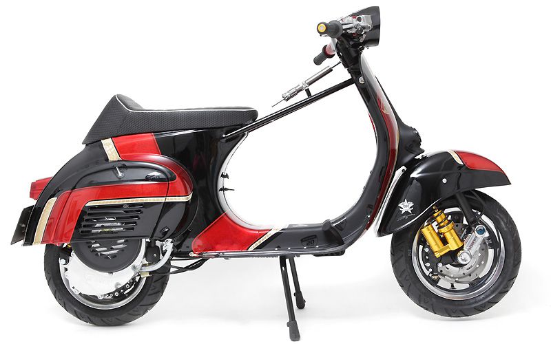
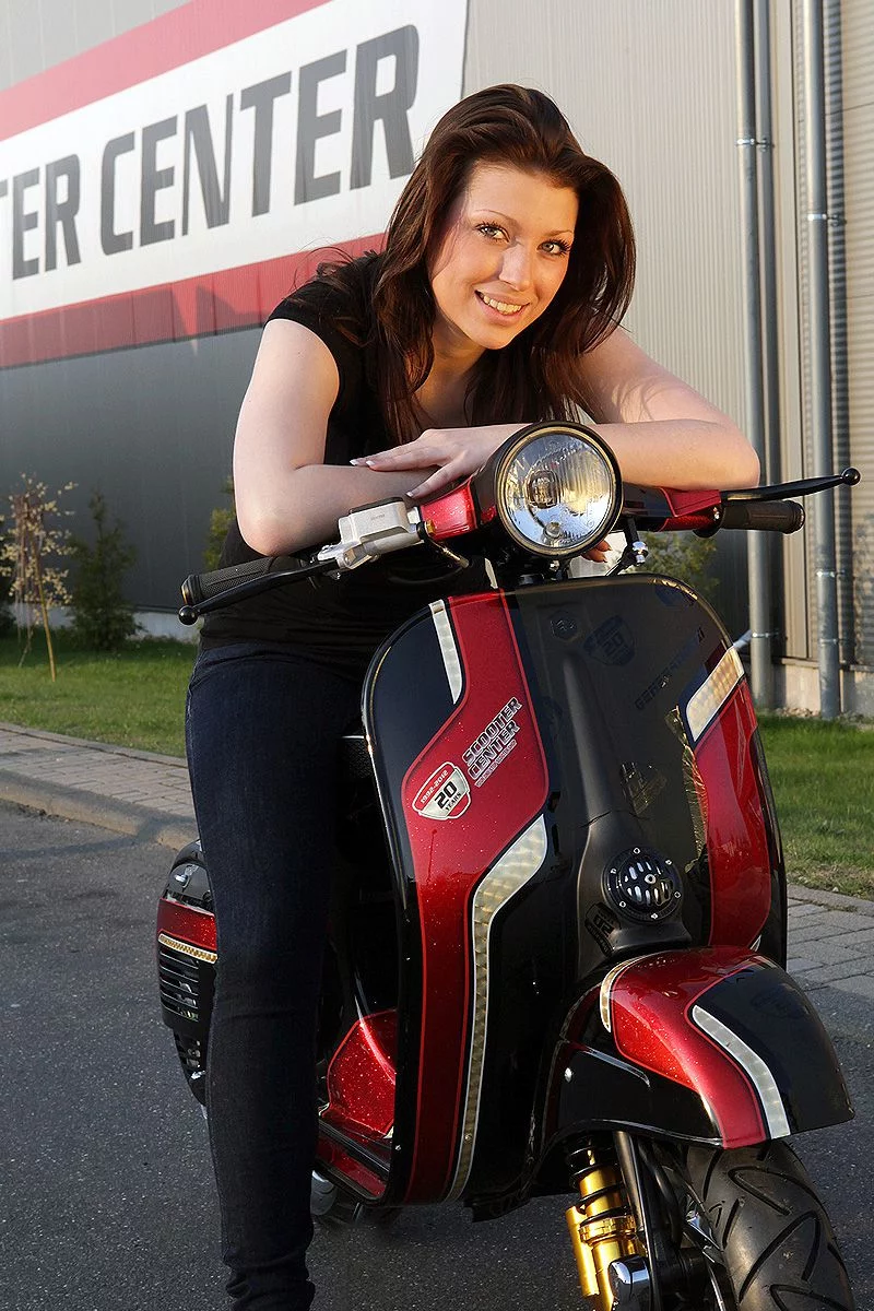
The history of the origins of the Vespa Generation XI

For our 20 year old we wanted to set up a special project. Until the beginning of January there was only the idea as such and no concrete ideas what exactly it should be for a scooter. It is only clear until the Custom Show in Ried / Austria The scooter should be ready on February 25.02.2012th, XNUMX. So a very sporty time limit to build a complete custom scooter from ZERO.

Vespa custom scooter generation XI

The starting shot was that Monday 09.01.2012

Disassemble the scooter

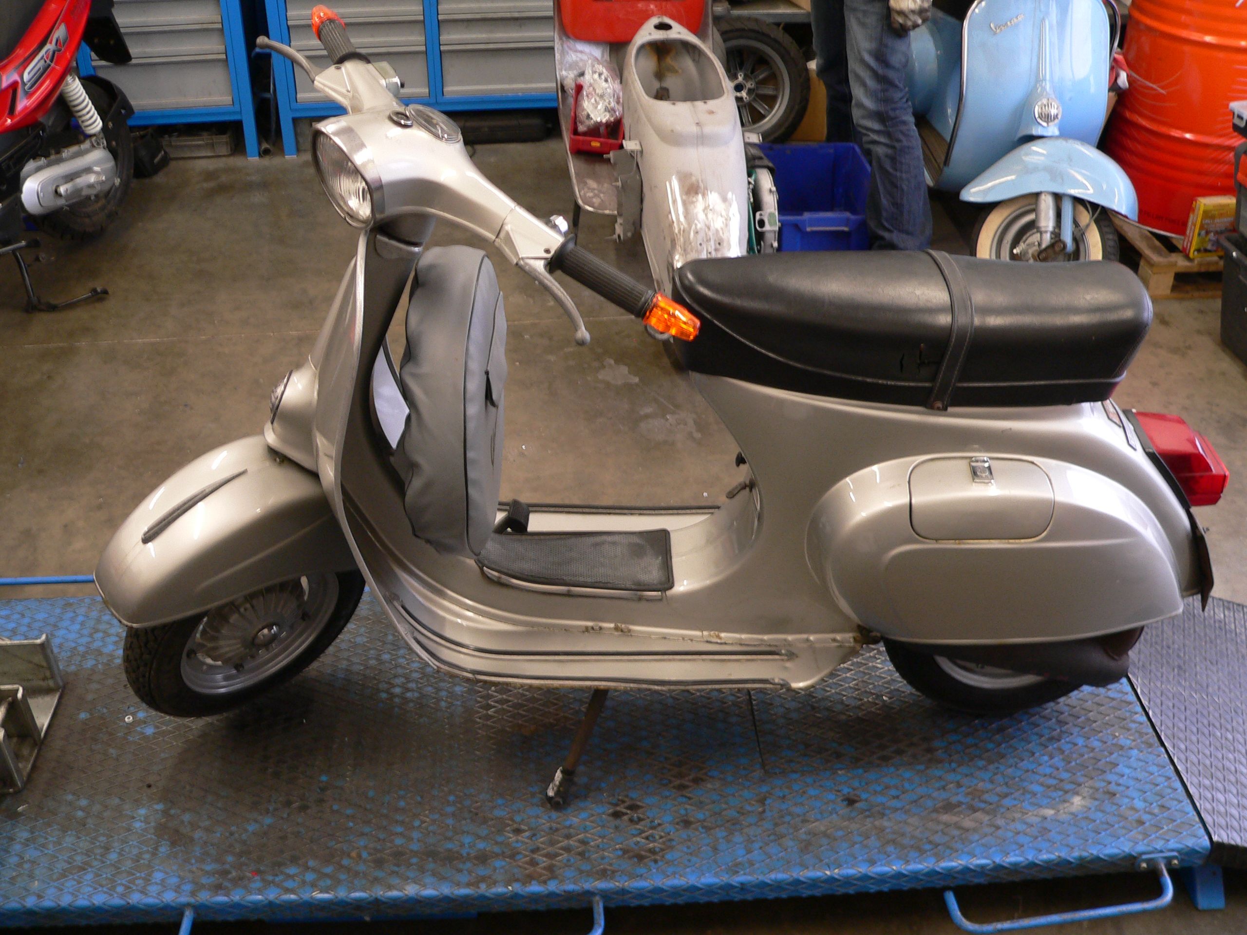
We chose a roadworthy one Vespa Primavera ET3 decided as a basis. The beauty was completely dismantled….


.... and after successful slaughter, the frame and all sheet metal attachments are sandblasted. The footplate and the frame tunnel are cause for concern, because only after sandblasting can you see how much sheet metal is left.

As long as the frame is sandblasting, you can worry about the “rest”. Hopefully enough of the frame remains :-). Since the direction of travel in this project is “Racer”, there is one disc brake inevitable. Maybe even front and back?

In order to be able to install a disc brake at the front, we need one PK-XL fork .

The original ET3 fork does not allow such a conversion. Apart from that, we also have something in preparation for the PK shock absorber.

For the motor, we opted for a complete CNC housing from Gernot Penn, who with his label GP One offers beautiful CNC parts for the Vespa driver. The engine case is intended for one Polini Evo cylinder and Polini Evo crankshaft be manufactured to match.


Friday 13.01.2012

Vespa sandblasting

Actually not a good date to pick up a frame from sandblasting. Fortunately and despite all fears, a lot of valuable Vespa sheet metal is left over after sandblasting. Of course, the elderly Italian lady reveals one or two dents after the over 30 year old paint is removed.

All in all, nothing serious.


Dirk, master of stripping pliers and body file, takes care of the sheet metal work.


Monday 16.01.2012

The scooter's brakes

Today we'll take them Bremsanlage in attack ... In order for the PK fork to stand properly in our frame, the fork must be processed. Without a corresponding processing, a “chopper chassis” would be obtained, because the PK fork in the lower area, i.e. the dimension from the lower bearing shell to the wheel center, is longer than with the V50 / ET3 forks.

To do this, we send the fork to Würselen, to the yellow company. There the lower bearing seat on our fork is turned off by 10mm and the steering tube is shortened by 25mm. Armin has experience with conversions of this kind and will do this work for us. The matter is of course subject to a certain deadline pressure, as the parts all have to go to the painter.

A separate wheel hub must be manufactured for the planned rear disc brake. To do this, we first have a sample made for the main shaft toothing - it sounds easier than it is now ... :-)

The pattern is produced by his racing driver team colleague Dennis using wire erosion. At this point we would like to express our big thanks to “Denni” because he is always the one who, when things have to be quick and parts have to be finished “by yesterday”, is absolutely conscientious, reliable and very quick to handle such “ Little things ”.


.... and it fits too.


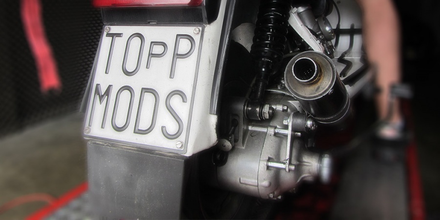
Fully hydraulic disc brake

The front disc brake should be operated fully hydraulically. To do this, it is necessary to attach a brake pump to the handlebar.
In our case, we'll choose one AJP brake pump with an 11mm piston.

For this will be suitable Brake pump adapter which, however, make reworking the handlebars unavoidable. Together with one Grimeca brake caliper With a 30mm piston, you should be able to achieve good braking performance with a pleasantly soft pressure point.

Here you can just see the adapter from below the handlebar installed, the original brake cable holder must be removed for installation:


You have to invest a few minutes in order for the adapter to fit into the recording as shown here.

All the better when everything goes well together afterwards.


Tuesday 17.01.2012


In the meantime we have received a message from Austria that the motor housings are in production.


Frame strut

So that our racer always stays on track during fast load changes and strong braking maneuvers, he gets a frame strut on which the later steering damper is mounted.


The double tube strut is attached directly to the head tube. A support on the thin sheet of the Frame tunnel Experience has shown that it does not last long and can tear off during heavy braking maneuvers. The struts are guided into the frame at the side below the seat bench nose and intercepted inside the frame with a cross strut.


For the steering damper, we attach a spacer nut to the left strut.


Weld everything briefly and then the strut is in place.


Wednesday 18.01.2012


Today the rims go for high gloss compression. At the moment you are still clad in Piaggio gray.


Thursday 19.01.2012


The fork is finally back. In order to accommodate the 11 ″ rims and to compensate for the resulting track offset of 8mm, we have to twist the fork slightly before welding it together. All parts are first put together dry to measure how far the fork / rocker has to be turned.


By turning the fork slightly, the shock absorber mount moves outward so far that the fender no longer fits. But more about that later, first the fork is welded. The fork is welded in layers together with the inserted sleeve, which is intended to reinforce the separation point.


After welding, the seam is smoothed and plastered.


Now for the fender, so that the PK shock absorber with its mount still fits under the fender, it must be widened. First the fender is separated. Then it is widened by approx. 10mm with sheet metal.


The whole thing is then made pretty and adapted to the fork. As you can see in the side view, the fender is unfortunately now attached to the frame. With something gentle persuasion but it all fits in the end ...


Friday 20.01.2012


By turning off the fork, the lower steering stop falls away. Of course, it has to be replaced again. Drawing the right position in the frame is a bit difficult.


Then the steering stop is welded on.


The ET3 originally has an ignition lock, since in the end we only use a kill switch, the hole in the steering head disturbs. Since we want to install a Fastflow fuel tap with a reserve indicator, the space that has become available is ideal for the indicator light of the reserve indicator. After the lock opening to be welded, the handlebars must be smoothed again and a suitable cutout for the indicator light be made.


Now that all the work on the parts to be painted has been done, the preparation for painting begins. The scooter should get its color scheme at Pfeil Design in Austria. But before the frame and the add-on parts are sent to the neighboring country for painting, the frame is filled and primed here on site.


Monday 23.01.2012


The frame and the attachments are primed and filled.


All the glory is packed in a wooden box and prepared for shipping to Austria.


Bon voyage!


Gernot just wrote that the motor housings are on their way ...
The Falc suction device that we want to use for the Polini Evo has already arrived.


Tuesday 24.01.2012


The rims are back from the high gloss compression :-)


The engine case has also arrived :-) It's really tough stuff ..


So that the rear wheel can also be braked hydraulically, I have to briefly tinker with a partial hydraulic system. Ingredients are the original brake pedal and the Brake cylinder of a TPH 125.


Looks like it even works :-)


Thursday 02.02.2012

Now that all the parts are at the painter, you can focus on the engine.

The racer should be driven on the road and over longer circuits.

That's why we put together a corresponding gearbox.

So that you don't always have the handlebars in your face during the expected performance when accelerating, i.e. the front wheel leaves the road, we take it Gear 1 and 2 from the DRT range to extend the two aisles.

Gears 3 and 4 remain original on the main shaft. The fully equipped main shaft is fitted with a DRT “Runner” countershaft combined, which in turn shortens gears 3 and 4. This allows you to get closer gear steps, which has a positive effect on the acceleration behavior of our racer and almost certainly leads to a big grin under the ' Helmet .


We also rely on one for the shift claw DRT execution

those of a reinforced switch spring is kept in check.

There are many different tools and measures to install the switch spring, we simply use a long SW5 socket from the Ratchet box.


So that you know where to put your thumb on it the next time you change claws Switching balls do not say goodbye to the earth's orbit, let's simply mark the installation position without further ado.


When assembling the gear wheels you should always check the correct installation position.


When all the gear wheels are threaded, that's it Set game.
With new ones Shoulder rings you can choose the game closer, because the shoulder rings still run in on the first few kilometers. Experience has shown that an installation dimension of 0,05mm-0,10mm is sufficient.


Monday 06.02.2012

And it goes on ...

Today the motor housing tries on the disc brake ...