Silver Fern project, motor complete 2 °
The next step is to install the clutch.
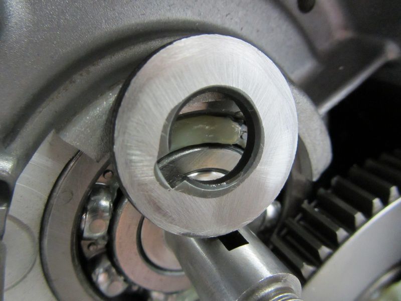
The spacer has a chamfer around the hole on one side. The side with the chamfer belongs in the direction of the crankshaft, as the crankshaft stub usually has a small radius at this point in order to counteract the notch effect.
The crescent wedge or Woodruff key should be pressed as far as possible into the groove of the crankshaft so that it does not stand up when the clutch is pushed on and damage the clutch hub.
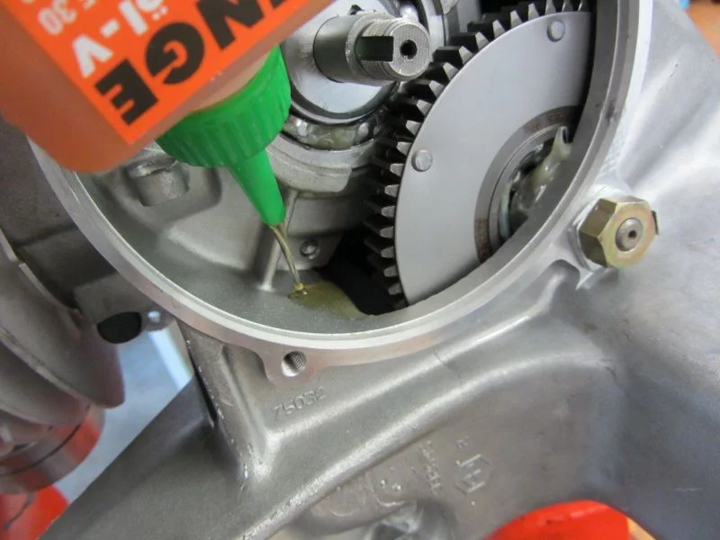
Before the clutch is installed, we still use the free access to the gearbox and fill in the gearbox oil.
As soon as the transmission oil is stowed in the engine, the clutch is mounted.
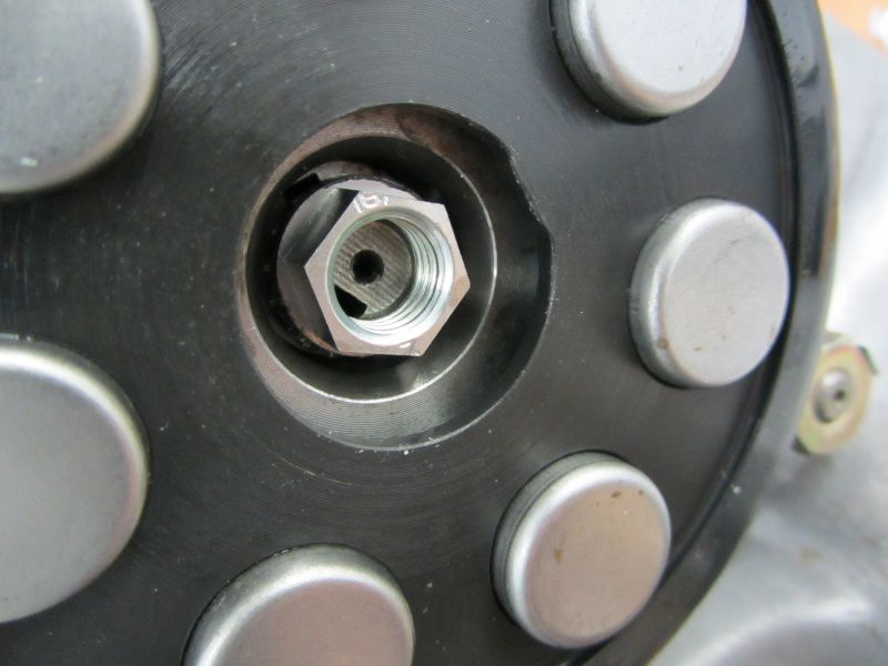
Fortunately, there are now other solutions than the well-known castle nut, which has certainly already driven one or the other Vespa screwdriver cursing insane.
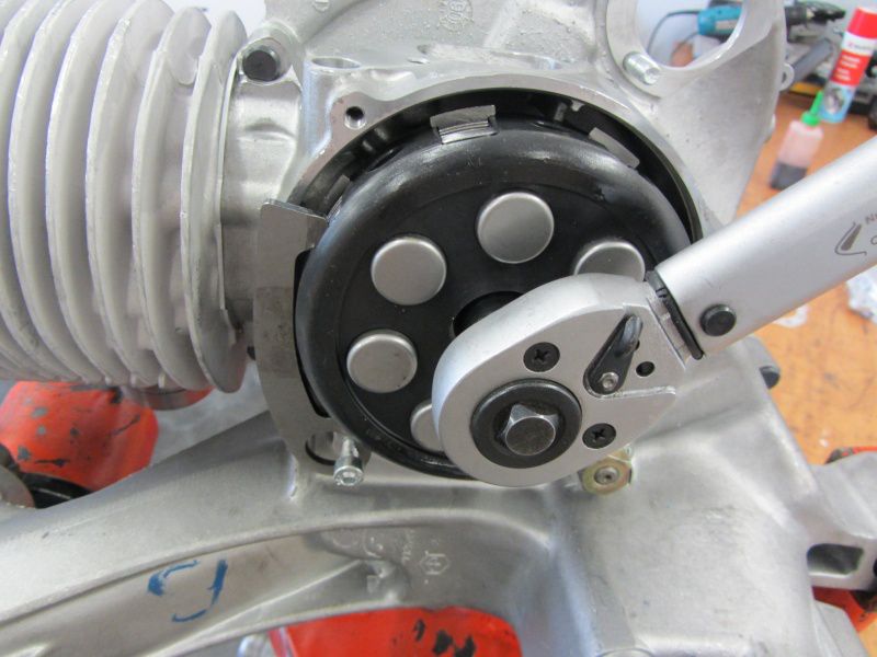
We have these nuts made in Germany. Unfortunately, elsewhere there are some Indian “qualities” on the market that cannot cope with the required tightening torque of 50Nm and stretch their arms.
Nut tight, now comes the thrust washer.
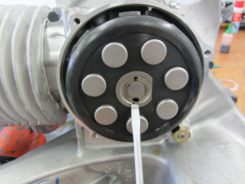
The retaining lug of the spring is guided through the larger of the two holes during assembly.
The pressure mushroom gets a touch of fat ...
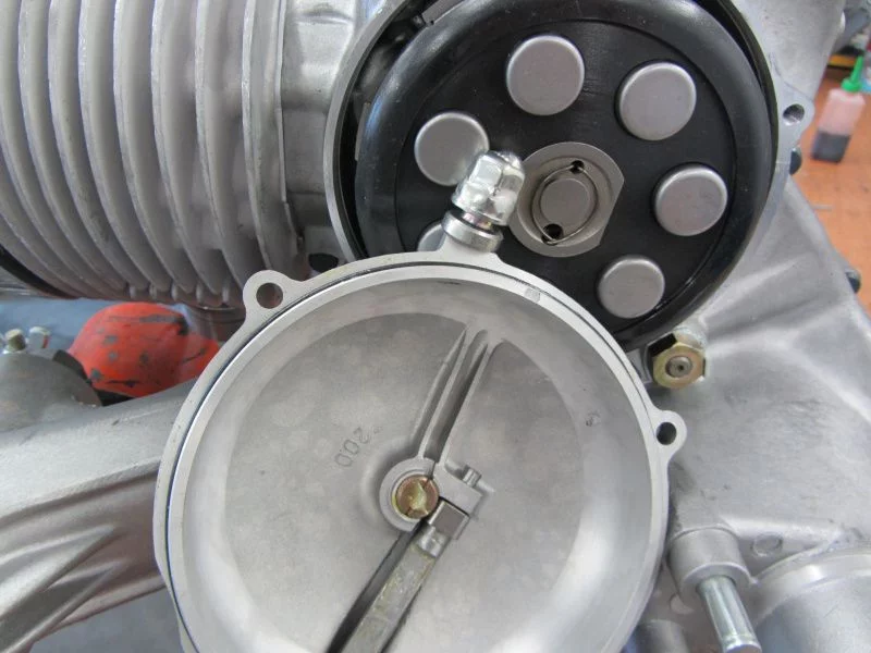
and then it goes to the membrane box.
As tested, the float chamber of the Keihin is located below the lowest point in the tank. Unfortunately not the influx.
In order to avoid that a small air bubble at this elevated point will stop the fuel flow later during operation, we have to equip the Silver Fern with a fuel pump.
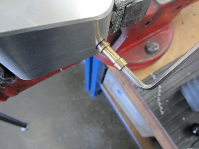
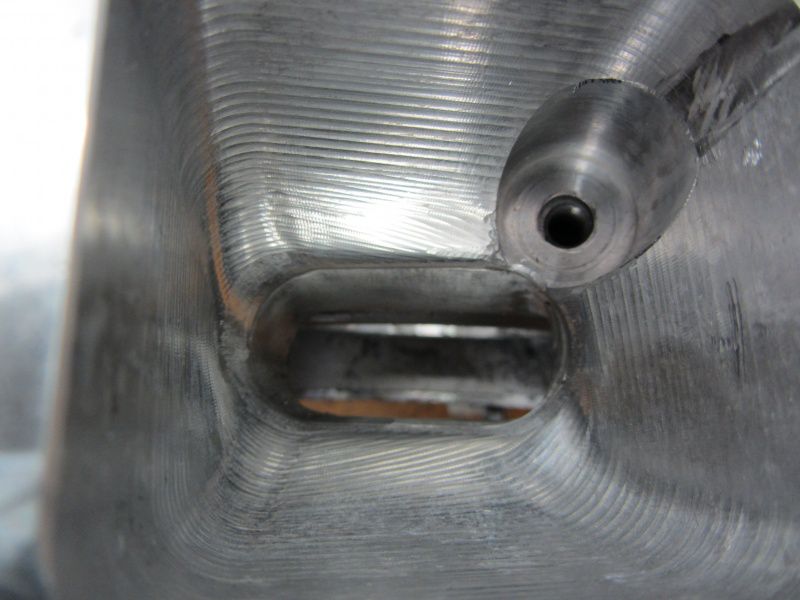
We put the vacuum connection in the membrane housing.
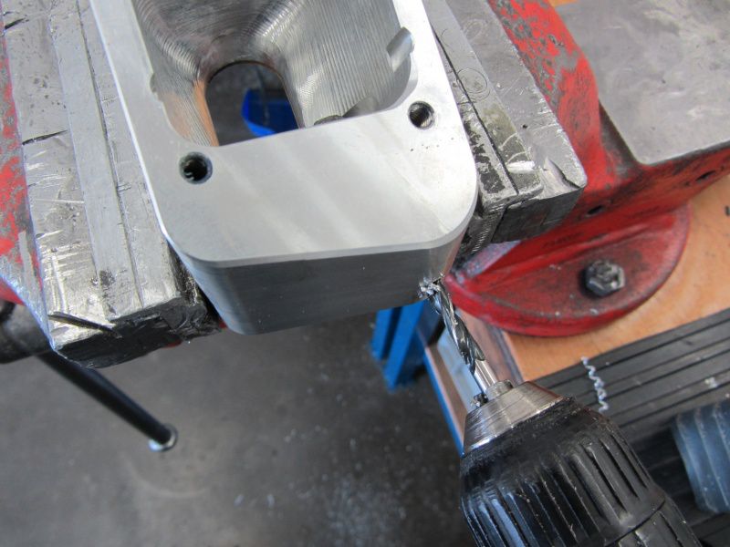
Drill…
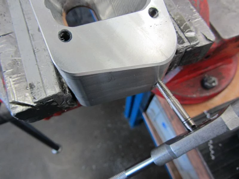
Insert the thread and ...
and use the countersink to create a small sealing surface for the cone of the vacuum connection.
The connection is screwed in with a little screw lock.
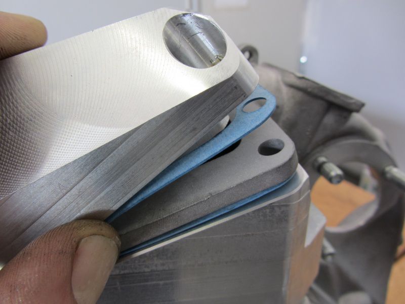
Then the suction device is installed with the membrane and seals.
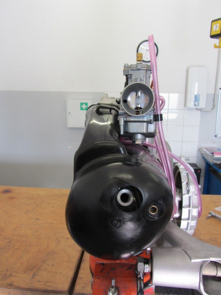
As a test, we attach the carburetor in order to make any necessary changes with the engine still removed.
We shape the cooling hood a little with the heat gun so that the carburetor is straight.
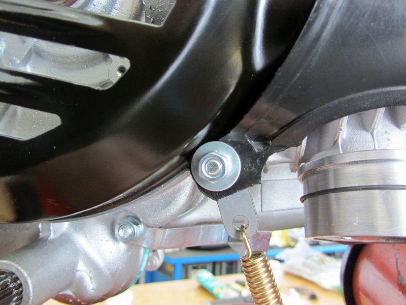
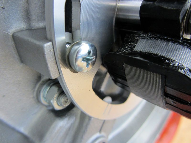
In the case of resonance systems, the manifold is often suspended with springs. For this purpose, a perforated plate is attached under the front screw of the fan wheel cover. If you just want to remove the fan wheel cover for checking or adjusting the ignition, you will usually be forced to unhook the spring every time. This sheet metal also works pretty well on the screw, since the surface is the soft plastic of the cooling hood and at some point the thread in the motor housing gives up.
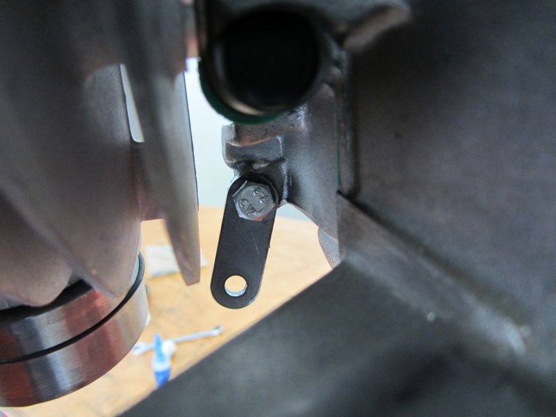
Therefore we now fasten the retaining plate for the spring from the inside with a screw.
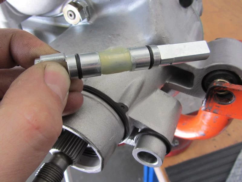
This, firmly glued in, then serves as a stud bolt on the fan wheel side.
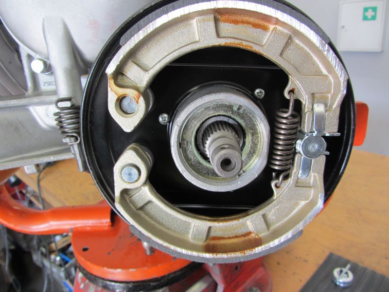
Installation of the rear brake system.
The recess on the brake cam is provided with a reserve of grease and installed.
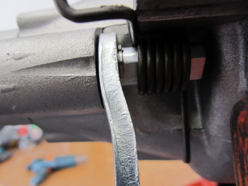
Brake arm, spring and finally the split pin.
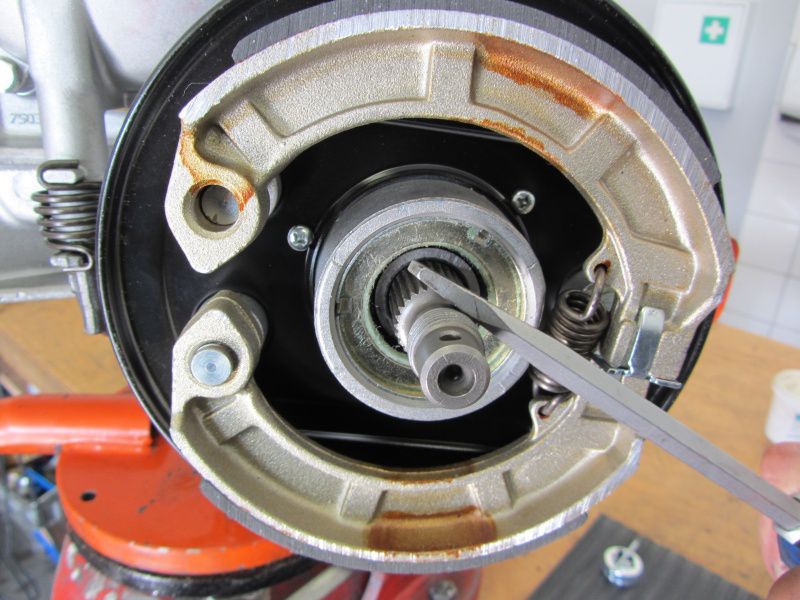
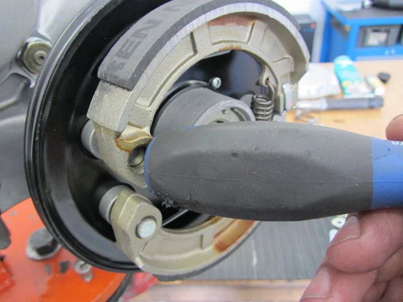
After the dust cover has been installed, it is the turn of the brake pads.
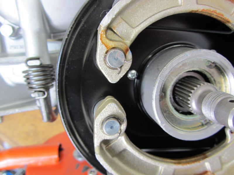
First insert at the bottom, then on top of the bolt ...
Then lift the top covering onto the cam with a screwdriver.
and then you can snap the covering into its actual position with a light bouncing blow. -Attention! Hands off!
Fuses are still on the bolts and you're done.
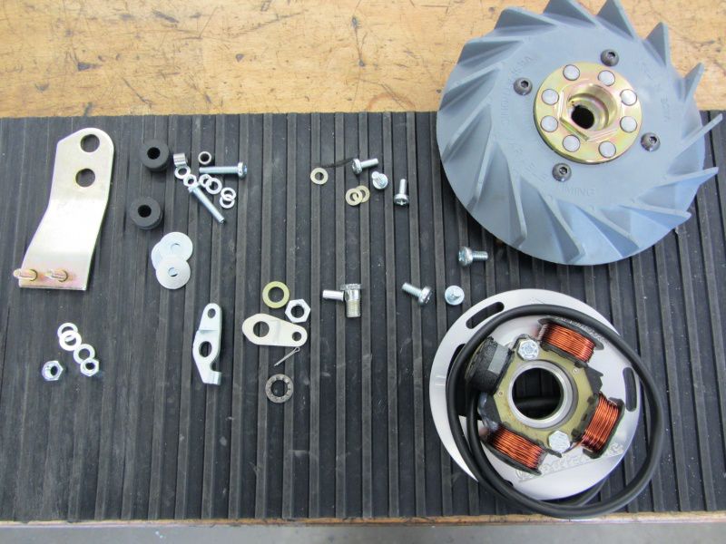
Here are the remaining parts that will be distributed on the engine.
The ignition system ..
is fastened with M5 screws and corrugated washers.
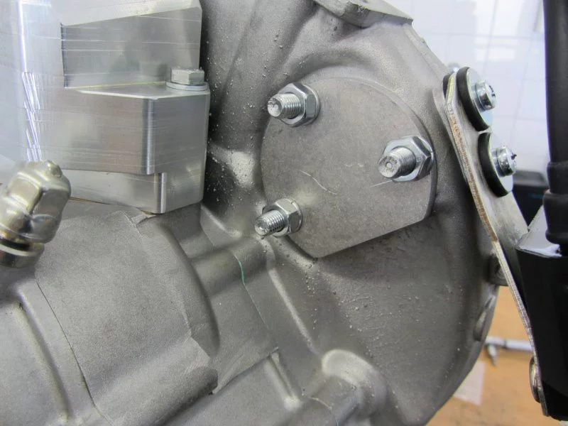
The retaining plate of the CDI is still mounted and because electric starters are only for .. well .., we don't need an electric start, so we close the hole with a cover plate.
Just quickly threw the fan wheel on it and then the wedding can begin.
Have a nice, sunny weekend!
Until Monday!
Alex







no respite - because progress is being made - things are moving forward !!
great engine for andy! I'm looking forward to seeing him in action !! keep it up alex !!
Mfg mukki