
Flasher conversion kit -BGM PRO, LED daytime running lights- Vespa GTS
Daytime LED conversion Vespa GTS with instructions
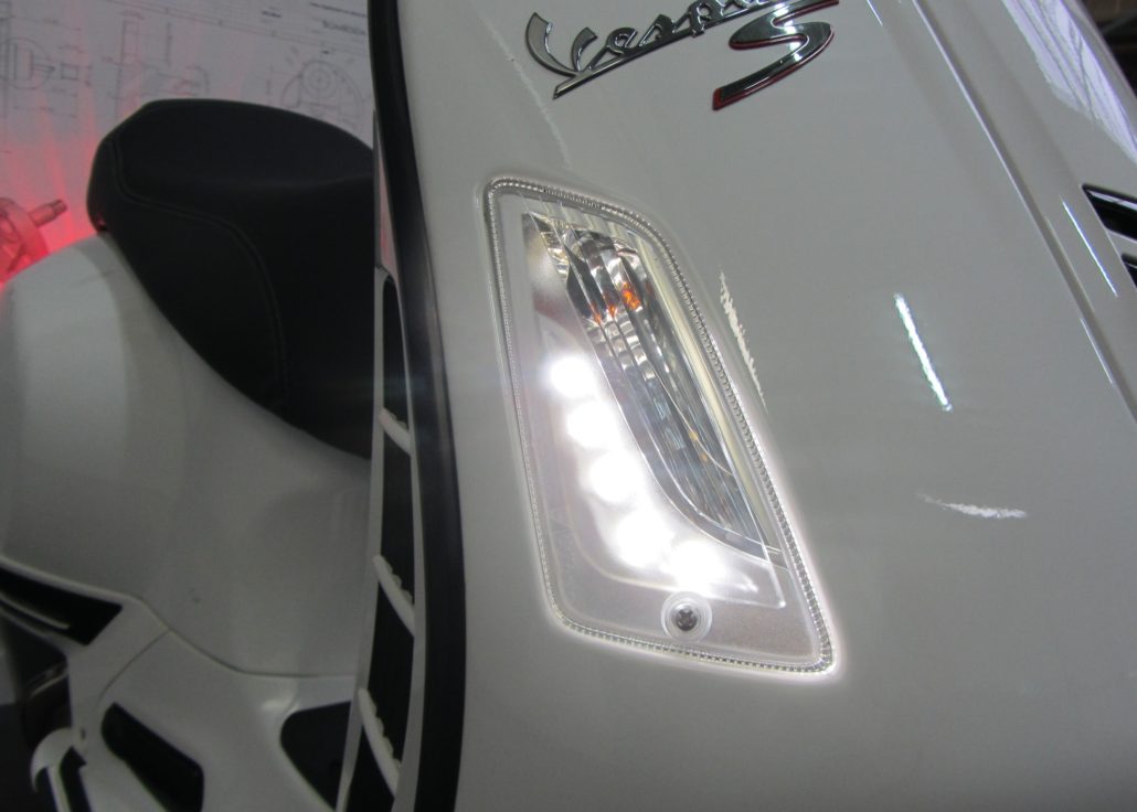
The newer Vespa GTS models from the year of construction 2014 have an additional daytime running light in the indicator lights. That looks great and offers additional security.
Update for daytime running indicators for Vespa GTS models built before 2014!
THE DESIRE
The Vespa GTS models from 2014 already have an LED daytime running light which is integrated in the indicators. These indicators also fit in all previous years of the GT / GTS / GTL series.
THE PROBLEM
However, the wiring is not very easy due to the different connector types used at the factory and would require irreversible intervention in the wiring harness.
THE SOLUTION
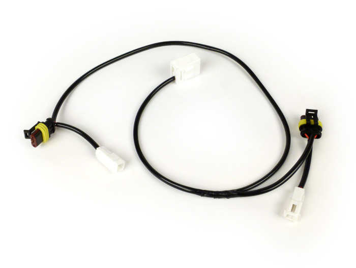
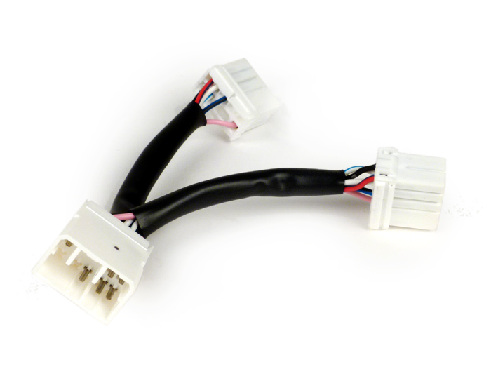
Our specially made adapter cable branch for your Vespa GTS before 2014 allows an absolute simple and comfortable Connection. This is suitable for all years of construction. Just plug it in and enjoy the great LED light:

THE perfect conversion set for your Vespa GTS LED indicators
So that this neat look and the daytime running light function can also be implanted in the GTS models built before 2014, you need our practical one Daytime retrofitting set for Vespa GTS consisting of the original Piaggio indicators and the bgm adapter cable:
Indicator set -PIAGGIO Triom, LED daytime running lights- Vespa GTS (2003-2013) - white - clear glass -
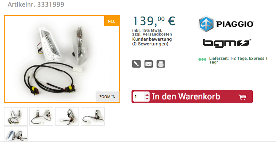
You can of course also get the cable individually if you already have the indicators:
PV60CKT Cable adapter kit for indicator conversion -BGM PRO, LED daytime running lights- Vespa GTS
PV60CKT cable adapter kit for indicator conversion -BGM PRO, LED daytime running lights- Vespa GTS (2003-2013)
feature
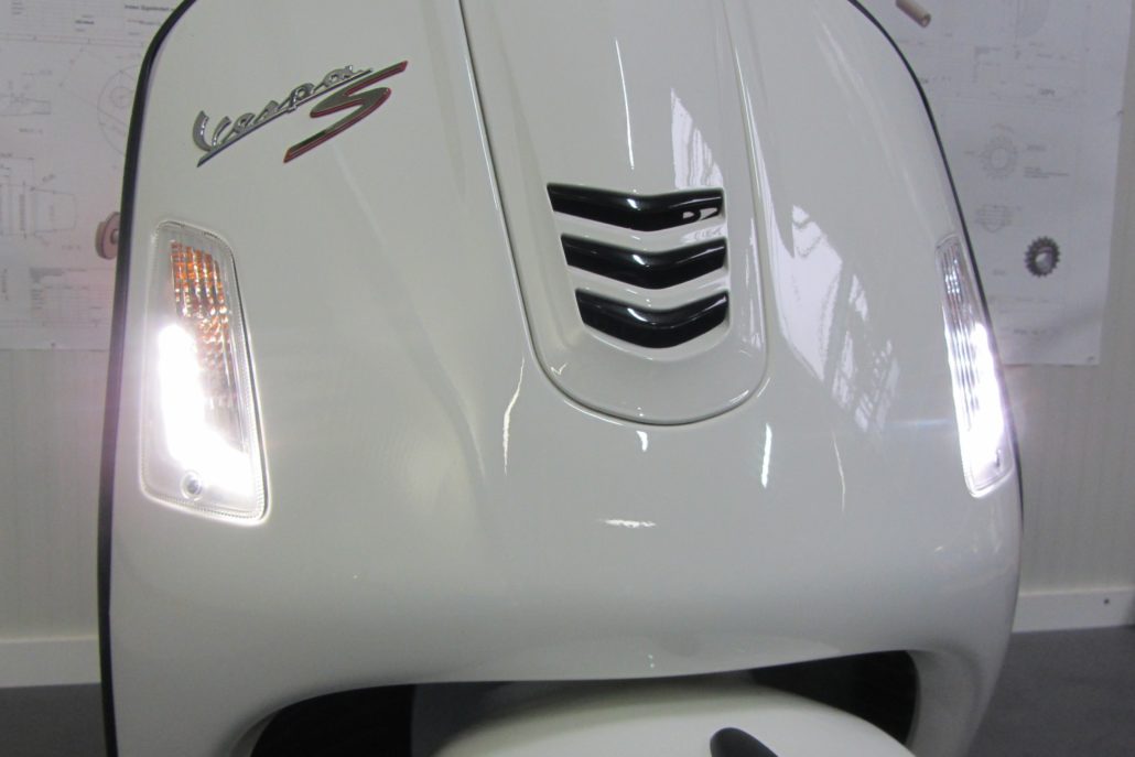
It works very simply: The daytime running lights of the turn signals are supplied by the light. When the ignition is switched on, the daytime running lights are also switched on.
The modification
To assemble the indicators and to lay the cable branch are simply only
- the maintenance hatch on the left
- the cascade,
- of course dismantled the turn signals.
- Then reassemble. Finished
The following tool is required
- Slotted screwdriver size 2-3
- Internal multi-point wrench TX25
- Phillips screwdriver PH2
Assembly work
To remove the maintenance flap, turn the handlebars to the right and remove the screw with a TX25 wrench.
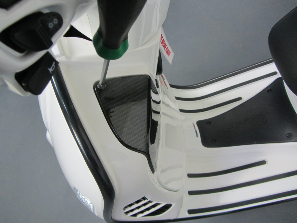
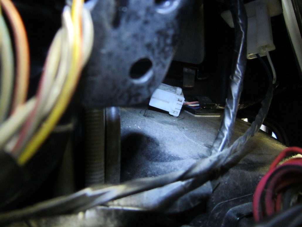
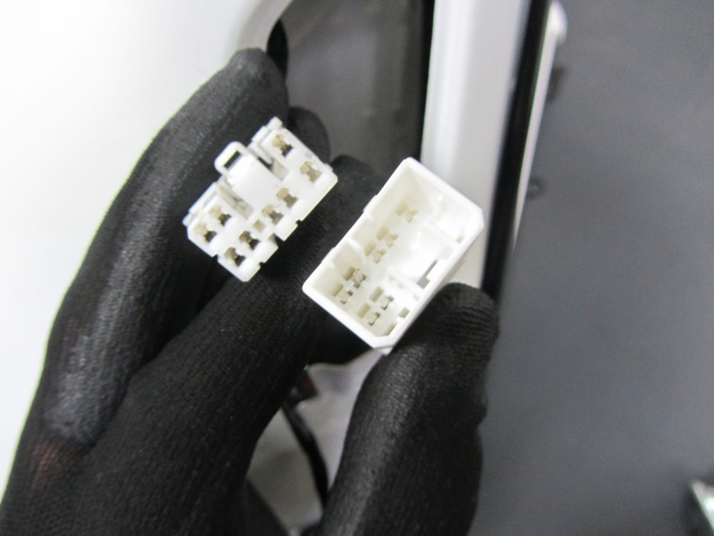
You then have to look for something in the bowels of the electrical system through the maintenance hatch. The object of desire is a free harness with a
8-way multi-connector. If the vehicle has an alarm system, it is plugged in there.
On some vehicles, this free cable branch is fixed to the glove compartment with a clip - here's a look through the front turn signal opening.
The Kasakde is only secured with an internal serrated screw (TX) hidden behind the Piaggio emblem.
The emblem has a small gap on the left-hand side in the direction of travel and can be lifted from there with a narrow screwdriver.
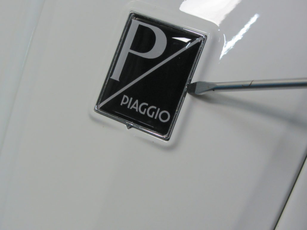
The only screw of the cascade is hidden underneath. This is released and removed with a TXS25 key.
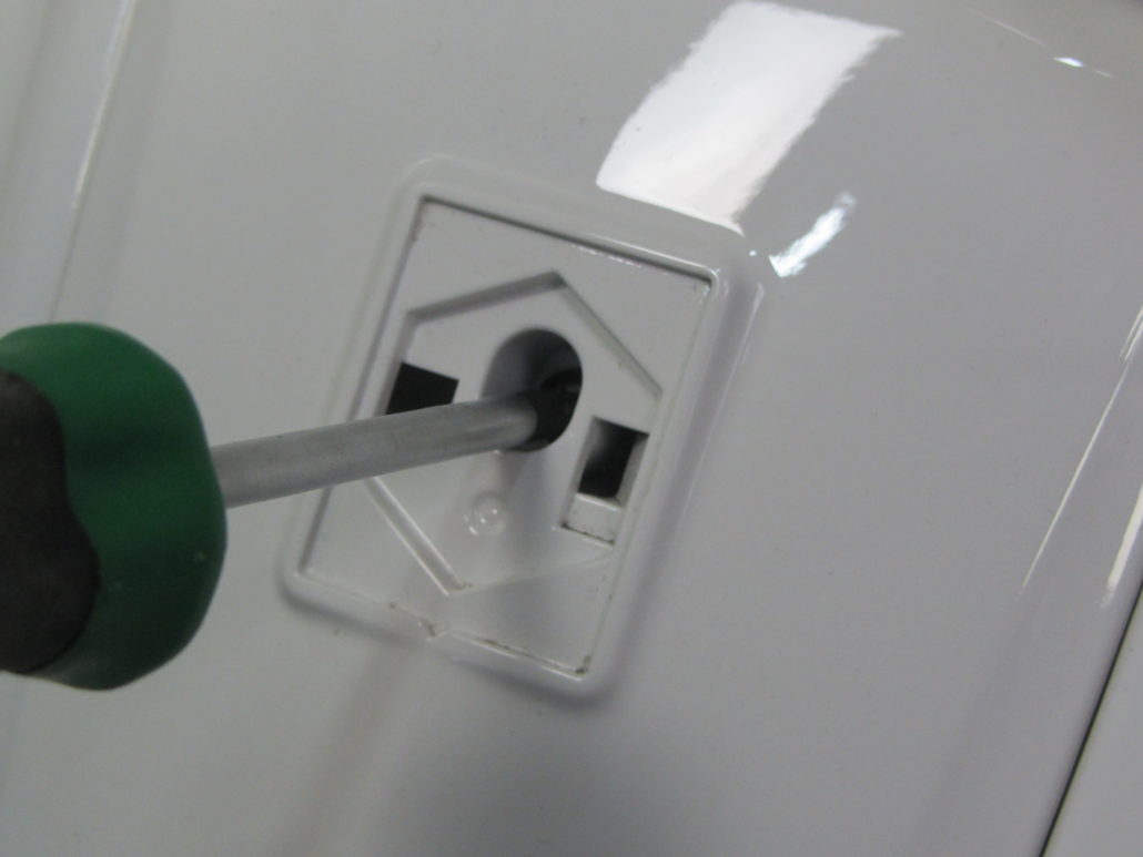
The cascade is removed upwards / towards the front.
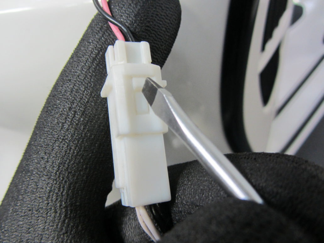
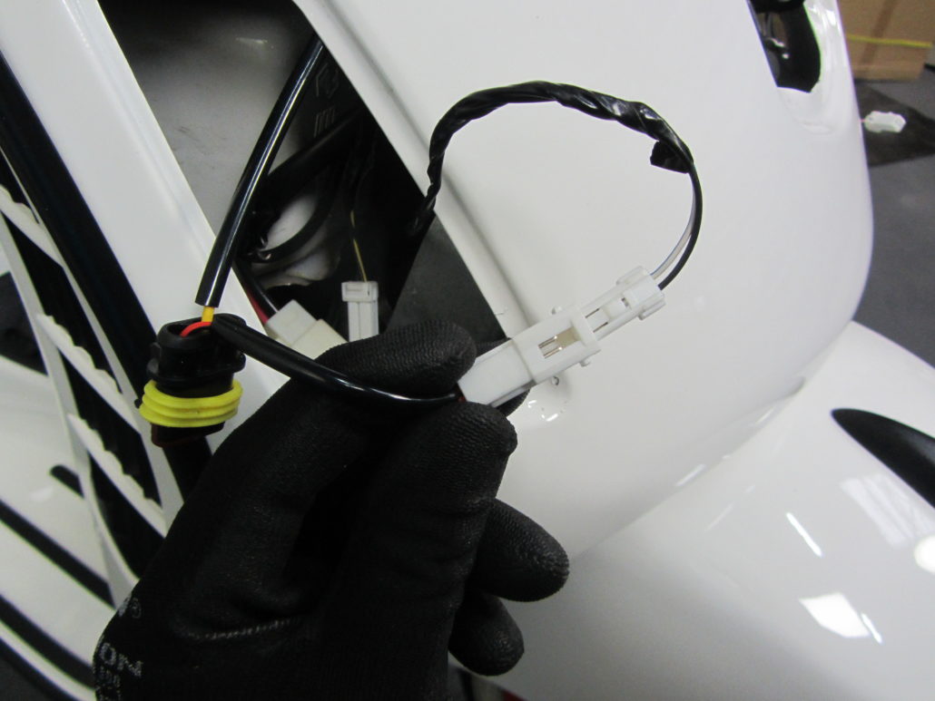
Dismantle both indicators with a Phillips screwdriver PH2.
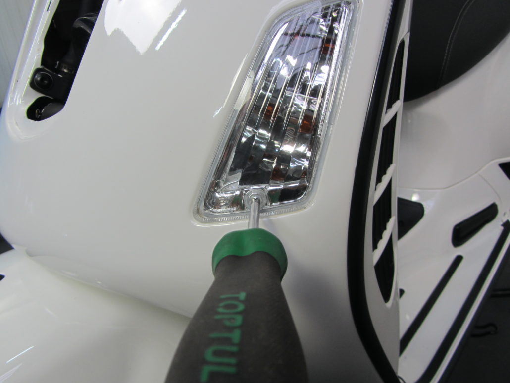
and disconnect the connector. The safety clip can be easily operated with a slotted screwdriver.
If both indicators are removed, the new cable branch is plugged into the 8-way plug.
Should the scooter come with a Piaggio alarm system be equipped, a so-called cable switch or Y-piece is required.
PV60CKTA cable switch -BGM PRO, LED daytime running light / alarm system- Vespa GTS (2003-2013)
The cable switch is simply plugged between the cable harness from the vehicle and the alarm system. The function of the alarm system is still guaranteed without restriction.
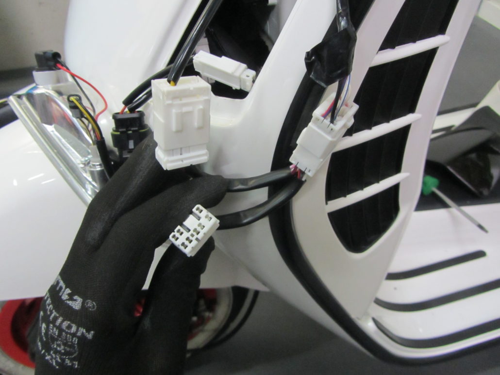
The longer end of the new turn signal cable branch is led behind the cascade to the right-hand side and there connected to the original connector and the new LED turn signal.
For the turn signal on the right side, the black multi-connector must be pushed out of the guide on the turn signal housing, otherwise the turn signal will not fit into the cutout of the frame.
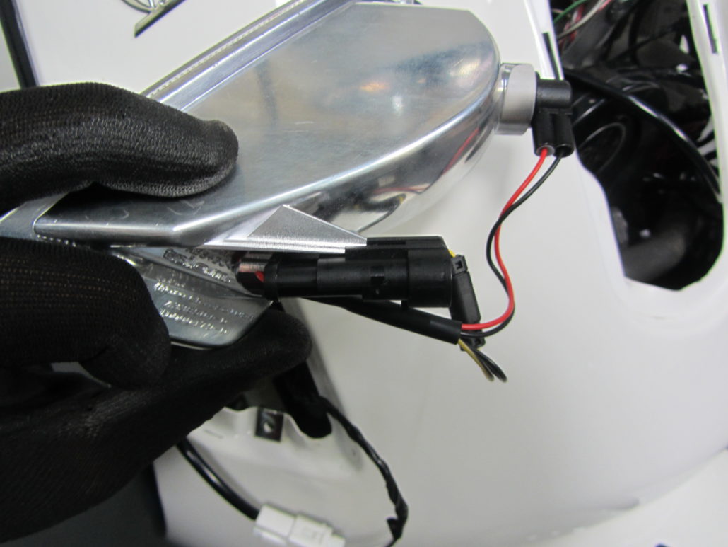
On the left-hand side in the direction of travel, the black multi-connector remains in the position on the indicator housing.
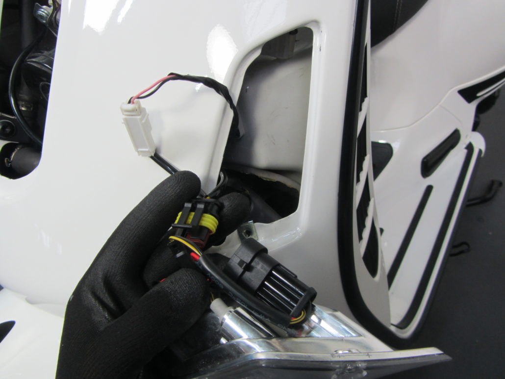
Once all the plug contacts have been connected, the indicators, maintenance flap and cascade are reattached.
Finished.


Leave a Reply
Want to join the discussion?Feel free to Contribute!