Complete the Silver Fern project, engine
We clean the motor housing thoroughly before assembly brake cleaner and compressed air, because after all we have produced quite a bit of aluminum chips.
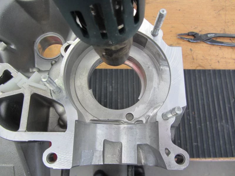
To install the bearings, we heat the motor housing with a hot air blower to approx. 90 °.
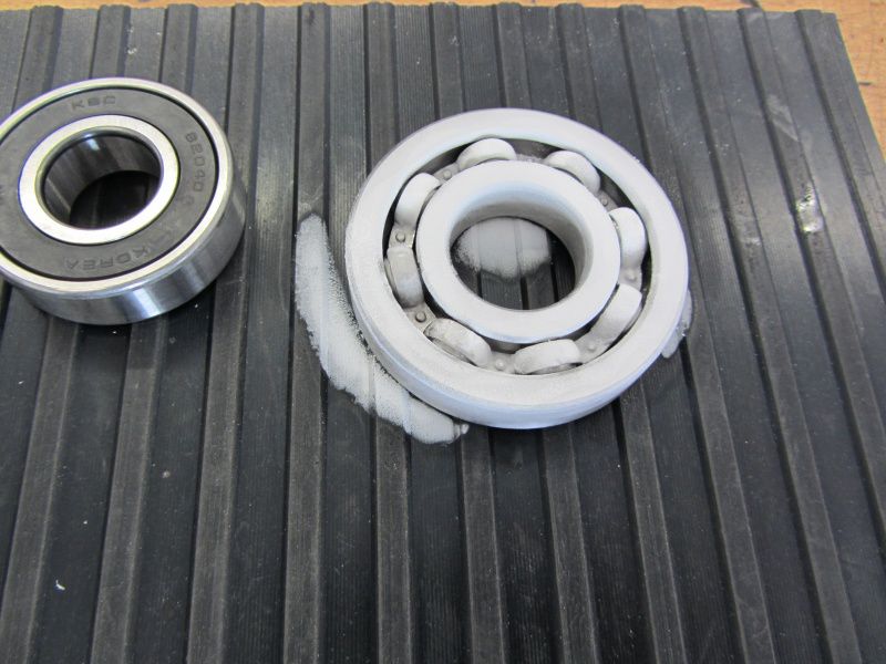
The ball bearings are with Cooler spray treated. Almost all of the bearings have been shrunk in this way.
The only exception is the B188 for the main shaft in the small, alternator half. We use that for the installation matching tool.
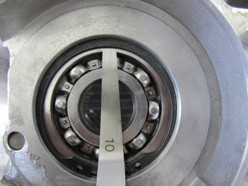
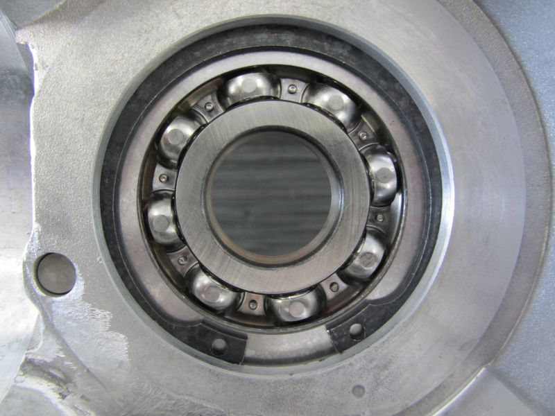
As soon as the bearing is on the coupling side, we use a feeler gauge to check the clearance to the circlip.
We also match the axial play Shims .
The whole action is intended to prevent the ball bearing from being able to move axially in the seat when the engine is warm and so sooner or later wear the bearing seat.
In the end, we come to 3 / 10mm with our motor housing, which has to be compensated.
We do the same with the 6204, the rear wheel bearing.
It continues with the shaft seals.
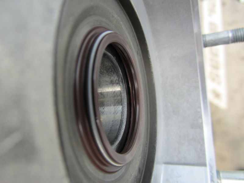
We use one to match the Lusso main shaft internal shaft seal.
One with on the crankshaft Metal shaft seal.
It is important to check after installation whether the shaft seal is in contact with the bearing.
If that were the case, the shaft seal would be destroyed within a short time by the frictional heat generated.
For the next step you should be a calm character.
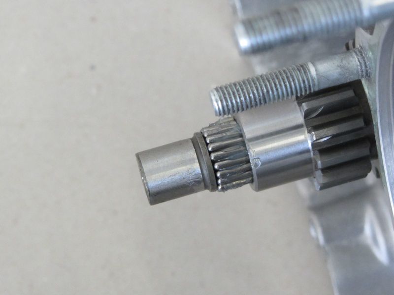
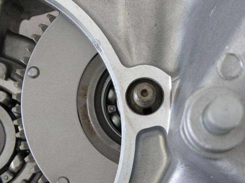
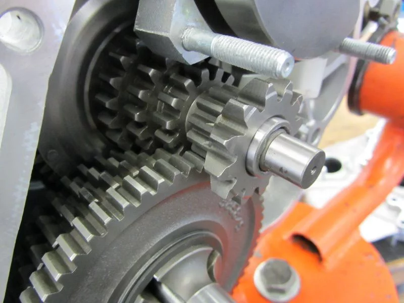
The auxiliary shaft is inserted with the axis into the motor housing so that the bearing surface still protrudes.
With a little fat they will be 21 loose needles glued to the auxiliary shaft axis.
As soon as all the needles have been sorted, the axis can be pushed into the housing as far as it will go.
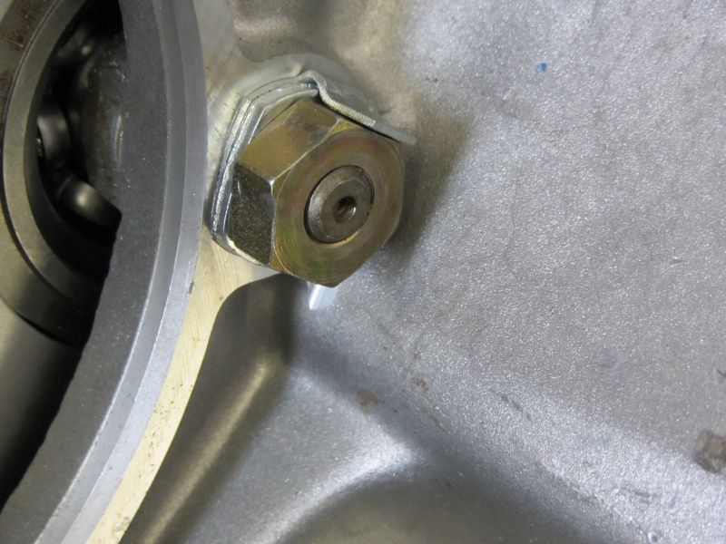
The auxiliary shaft axis has a recess for the nose on the locking plate.
Together with the washer, the axle is then tightened to 35Nm and secured.
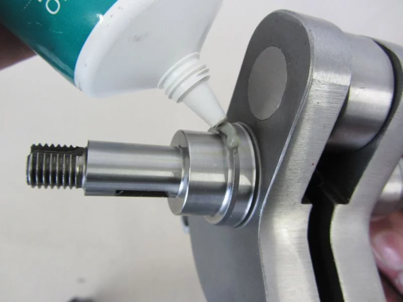
To install the main shaft, we grease the chamfer for the shaft sealing ring so that the sealing lip does not turn over when it is pulled in.
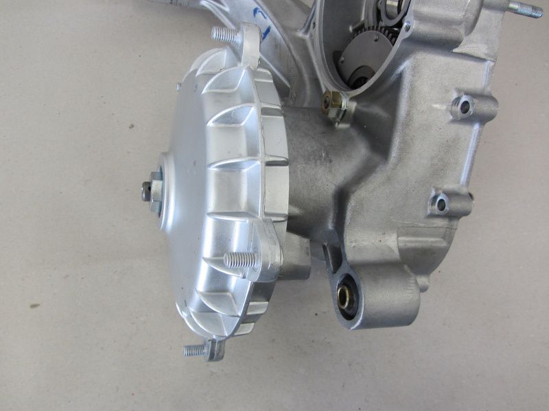
brake drum let's pull the main shaft into the bearing.
The crankshaft still needs the bearing ring pitched .
The orientation of the bearing ring on the shaft is ensured with a spacer gauge.
On the one hand, so that at some point later we can replace the bearing ring with the puller and, on the other hand, so that the bearing ring sits far enough in the bearing.
Where we have the great piece in hand, we can make further preparations.
The Silver Fern is supposed to be used by a Vespatronic be ignited.
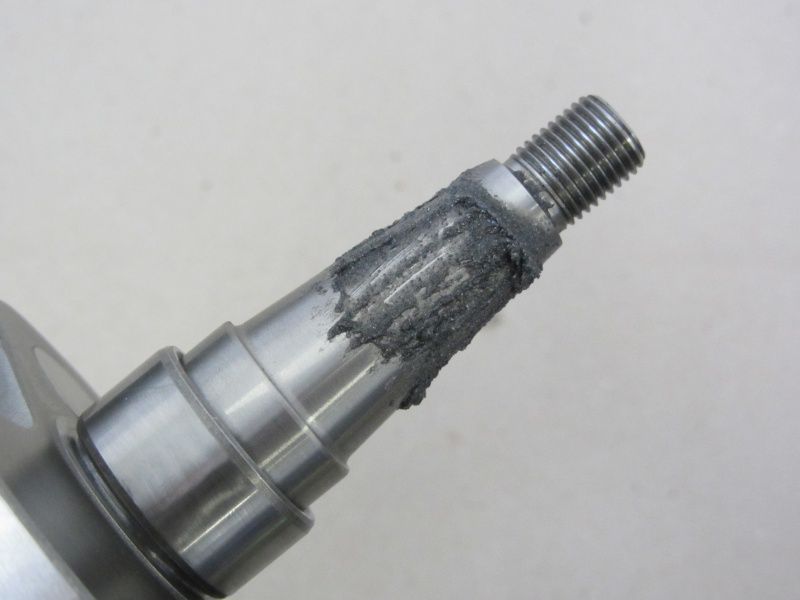
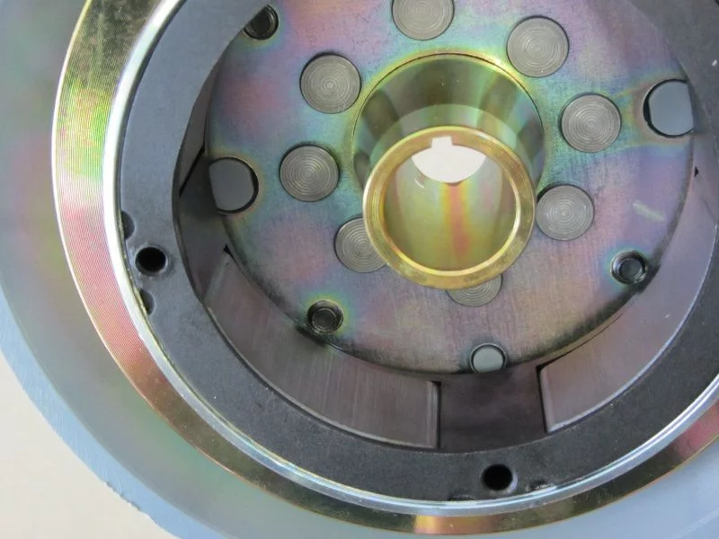
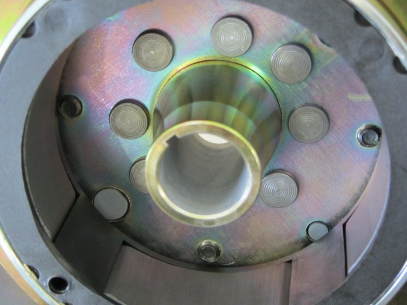
To be on the safe side, we grind the pole wheel of the Vespatronic Valve grinding paste so that any angle errors in the cone do not cause damage.
As soon as a uniform contact pattern emerges on the surfaces in the pole wheel and the crankshaft,
the cone should “glue” when put together.
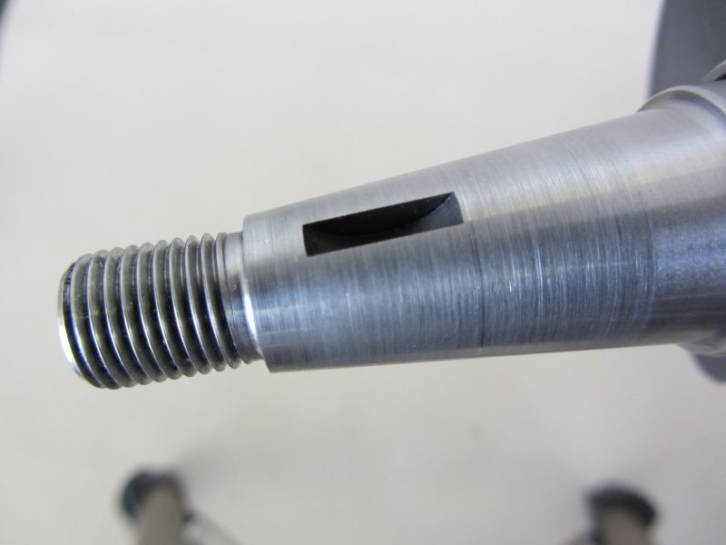
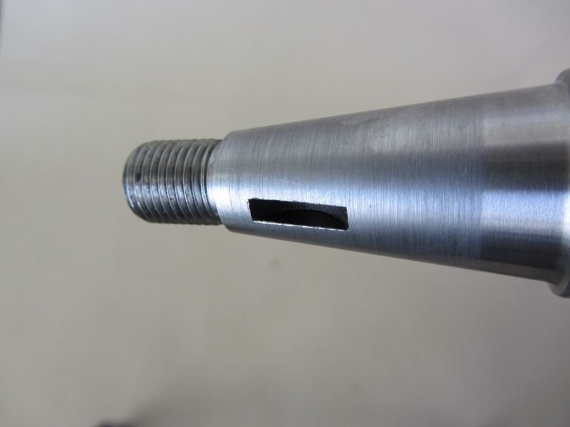
Sometimes it is totally annoying to use the crescent wedge in the installed state with new crankshafts, because it does not seem to fit. This is often due to a burr on the keyway that spoils the installation.
Therefore we deburr the keyway on the Lima side.
Before inserting the crankshaft, the chamfer for the shaft sealing ring is also provided with grease here, as on the main shaft.
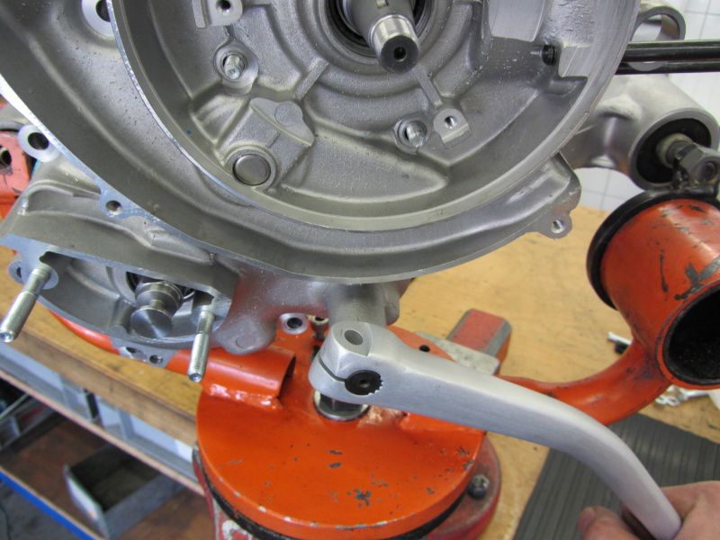
We put the half of the housing, now complete with the crankshaft, into one Motor mount.
This is much easier to screw afterwards.
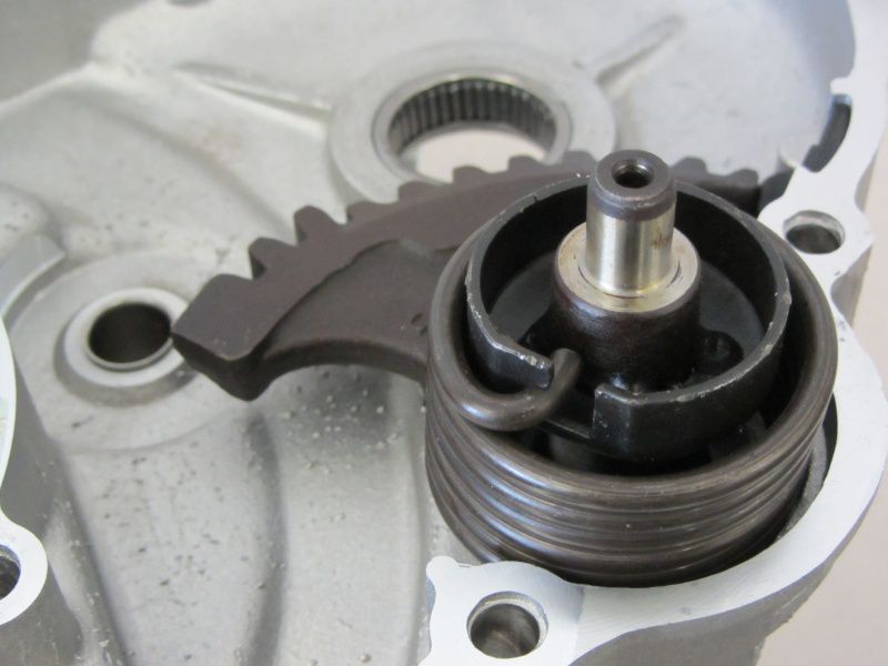
The second half of the housing is provided with an O-ring for the kick starter shaft, the same and the associated spring.
Uh! don't forget - that Kickerl! The pinion should be placed on the auxiliary shaft with a little gear oil.
We glue the pressure spring for the pinion with grease in the small half of the housing.
All open ball bearings also get a little lubrication so that there is no insufficient lubrication during the first few revolutions until the oil has spread.
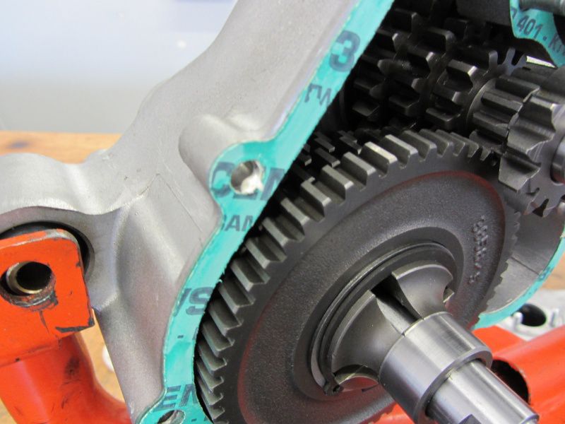
The Housing seal is fixed with grease so that it does not slip when the halves are pressed together.
When pressing the housing halves together, it is necessary to use the Kickstarter to be pressed briefly so that the pinion can jump behind the kick starter segment.
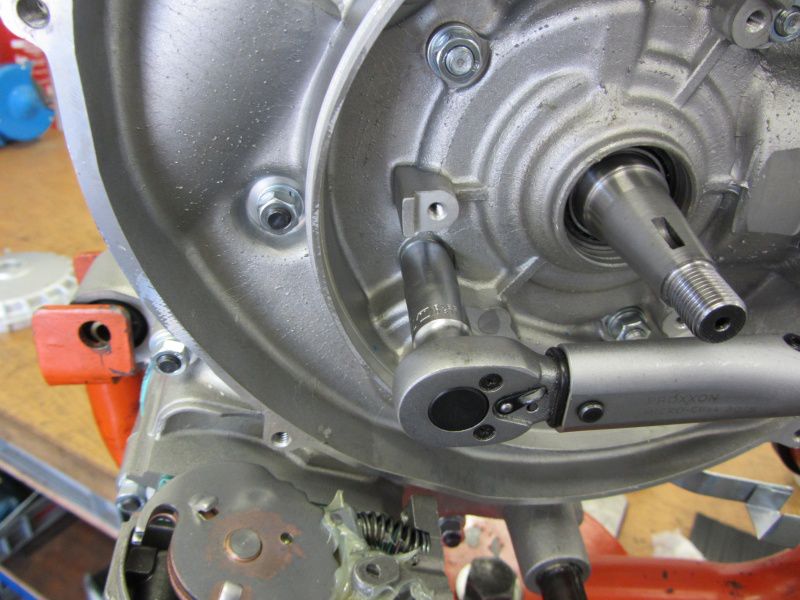
As soon as the housing halves are in contact with tension, we put the Housing bolt .
The bolts are tightened step by step up to 12Nm.
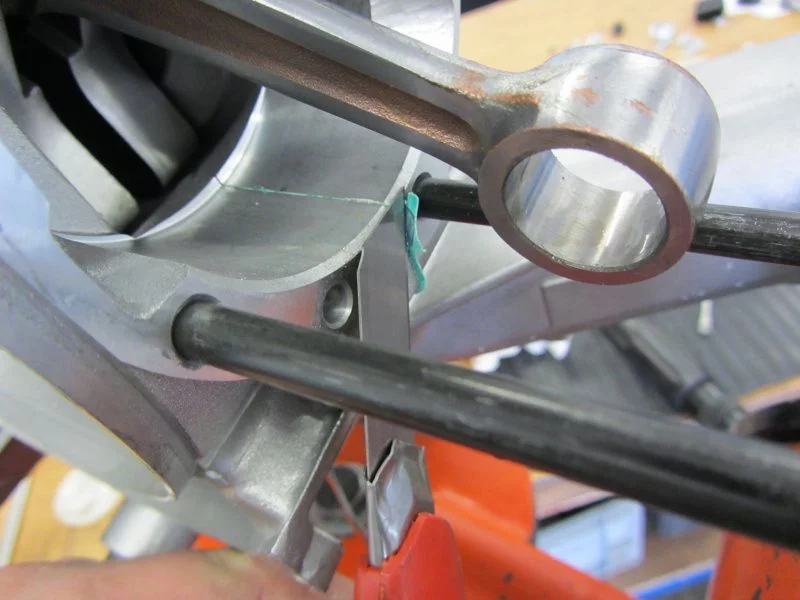
Cut off the overhang of the seal.
and then you can continue with the assembly of the piston and cylinder.
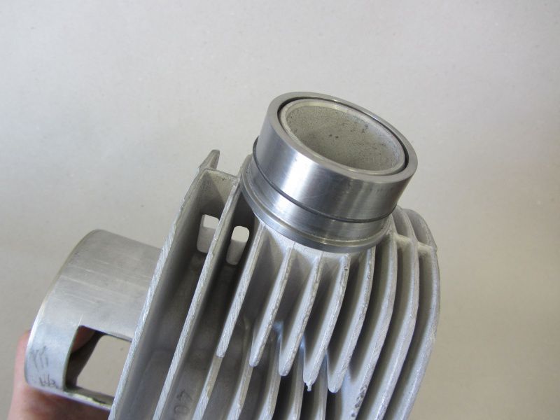
The cylinder and the outlet port of the Newline are quite “close” friends, so it is advisable to try the port on beforehand.
In the assembled state it would be a bit of a nightmare to machine the nozzle ...
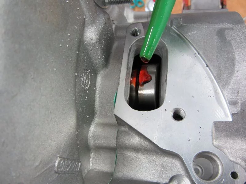
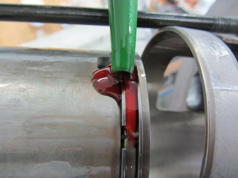
Upper and lower connecting rod bearings get something Motul with me for the first few meters.
Just like the piston pin, rings and the cylinder liner.
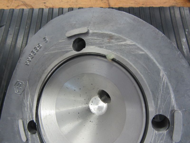
We grease the O-ring in the cylinder head into the groove so that it does not slip and get damaged during assembly.
Tightened crosswise step by step down to 20Nm, everything should also be tight here.










Leave a Reply
Want to join the discussion?Feel free to Contribute!