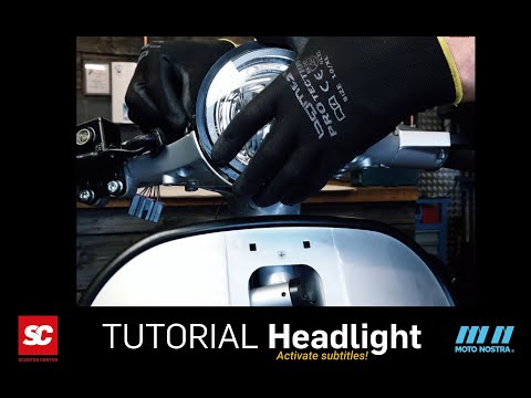
Vespa PX LED headlight
In this Vespa tutorial video we show you how to install our Vespa PX LED headlight for the Vespa PX. the MOTO NOSTRA HighPower LED headlight itself can also be installed in other cars (Lambretta, Vespa GTS, Sprint, Rally). With the included car specific frame, the installation of the Vespa PXLED headlight as eg Vespa PX LED headlight is very easy
CONTENT
WHY AN LED HEADLIGHT ON THE VESPA?
The limit with conventional Bilux bulbs is at most scooters a headlight bulb with 45/45 W. The 80 W to max. 120 W ignition does not give more. The luminosity measured in lumens is less than 400 and the LED headlight has a luminosity three times as high (1300 lumens). The power consumption is only 20 W. This corresponds to the luminous efficiency of a conventional 100 Watt spotlight. This means that with a given alternator/power supply a considerably better illumination can be achieved. In addition, more capacity remains for other consumers
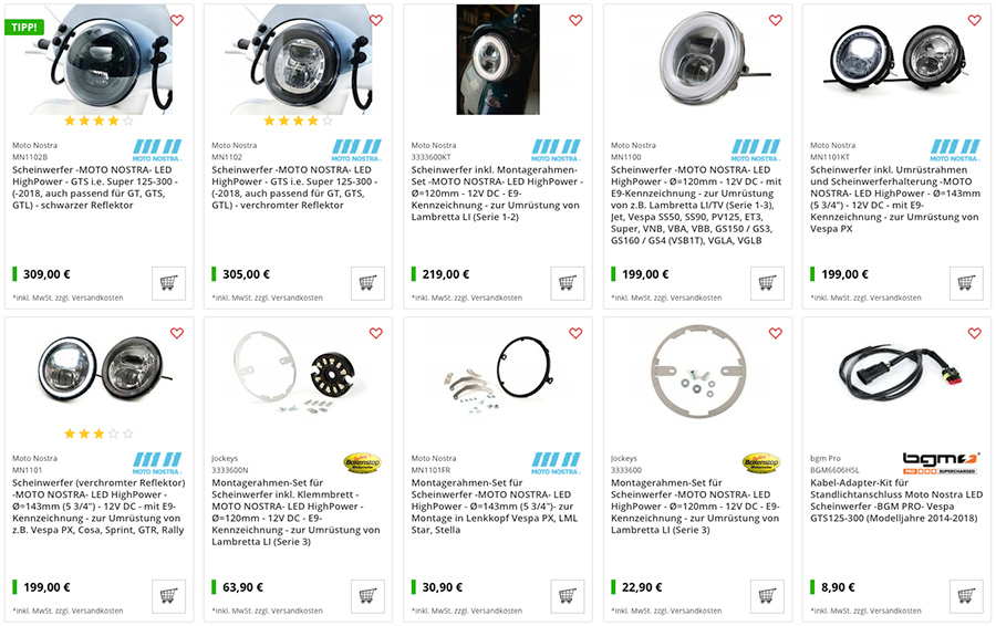
PARTS LIST / SHOP
Parts used in this video
- LED headlights incl. Conversion frame Vespa PX and headlight bracket -MOTO NOSTRA- LED HighPower
Item number: mn1101kt
- Ignition switch -VESPA 4-cable- Vespa PX Lusso (from year 1984 up)
Item number: 9520133
- Light switch -GRABOR- Vespa PK125 XL / ETS, Vespa PX Elestart (1984-1998) - 10 cables (DC, models with battery, normally open)
Item number: 9520145
- Rubber flasher relay Vespa PX
Item number: 3330940
MOTO NOSTA LED HEADLIGHT!
LED headlamp with E9 marking (road approval) and high-intensity main / dipped beam. Additional feature is a separately switchable position light. With a diameter of 143mm it also fits perfectly in the steering head of the PX and Cosa models as well as in the lamp bezel of eg Vespa Sprint, GTR and Rally.
TECHNICAL DATA
Luminosity 1300 lumen Voltage: 12 Volt DC (direct current) Power consumption: 1.8A / 1.3A Power consumption: 21.5W / 15W / 1.9W Diameter: Ø143mm Overall depth body: 54mm (measured from headlight ring without glass bulge) Overall depth overall : 79mm (measured from headlight ring without glass bulge with cable entry)
NOTES
The LED headlight works exclusively with direct current, therefore it needs a battery or another equivalent power source with 12V DC. Operation with an AC power source will result in immediate failure