Silver Fern project, gearbox, clutch, primary drive
The selection of the gearbox depends on the engine concept or the expected performance and the respective application.
Until today there have been repeated attempts to improve the poorly graded PX transmission for tuned engines.
Above all, the legendary 5-speed gearbox on which several manufacturers failed over the years.
Some rare Vespa Sprint transmissions had useful gear steps. Unfortunately, these gears are
Not necessarily for today's performance-oriented engines due to the design.
Meanwhile there are from DRT a secondary shaft which offers a better gear ratio.
Because the gears slip closer together, the final gear ratio is relatively short.
However, this can be counteracted with an extended primary gear ratio.
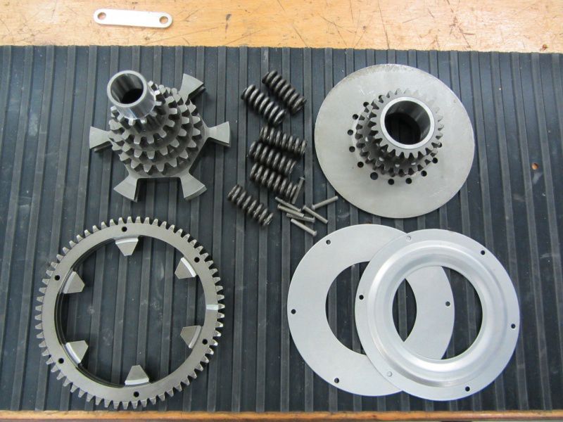
So our primary drive consists of the following components:
Malossi primary 24-63, with clutch pinion, springs and cover plates.
Secondary shaft DRT “Spitfire”.
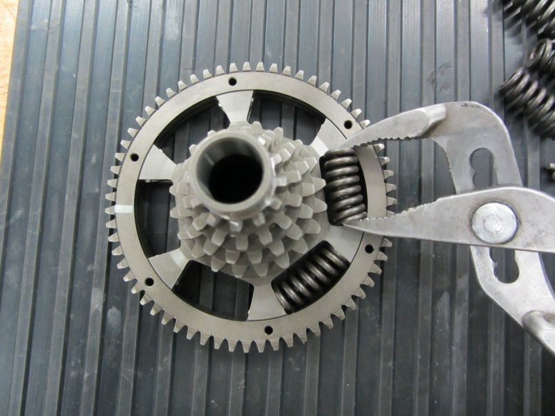
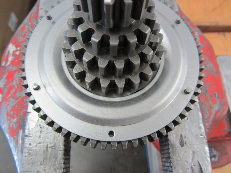
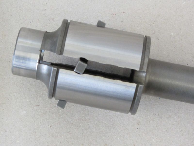
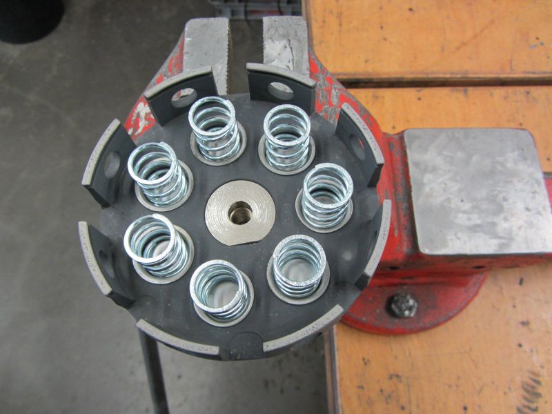
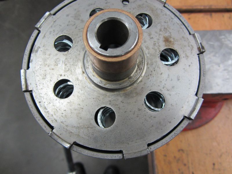
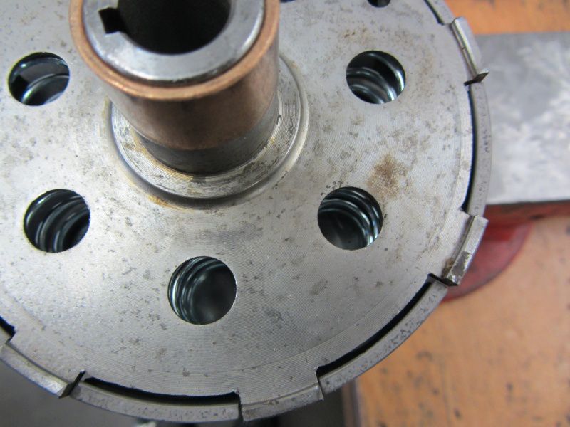
The primary wheel is threaded into the Christmas tree, which is what the secondary shaft is called, and the springs are inserted.
The springs are best used on a non-slip surface and a pair of pliers.
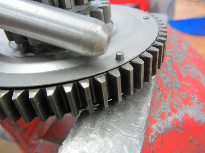
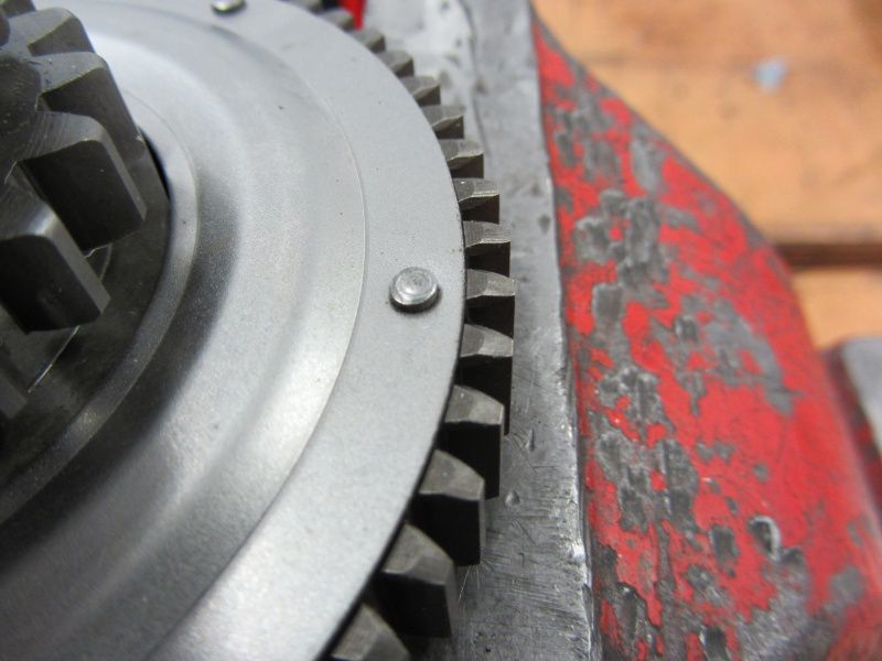
When all springs are in place, the cover disks are riveted.
The flat cover plate is installed in the direction of the clutch, the stepped plate in the direction of the gearbox.
So that the cover disks do not slip when riveting and cover the holes for the rivets, it is best to use several when riveting Niete employed.
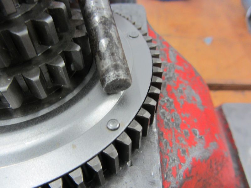
The rivets are first compressed with a rivet head. You should proceed in the same way as when tightening the cylinder head nuts - so always next, always compress a rivet on the opposite side.
After all the rivets are in place,
all heads are flattened with a flat punch so that there are no space problems in the motor housing later.
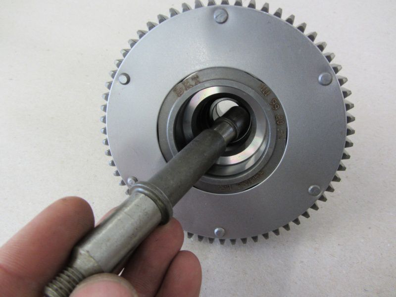
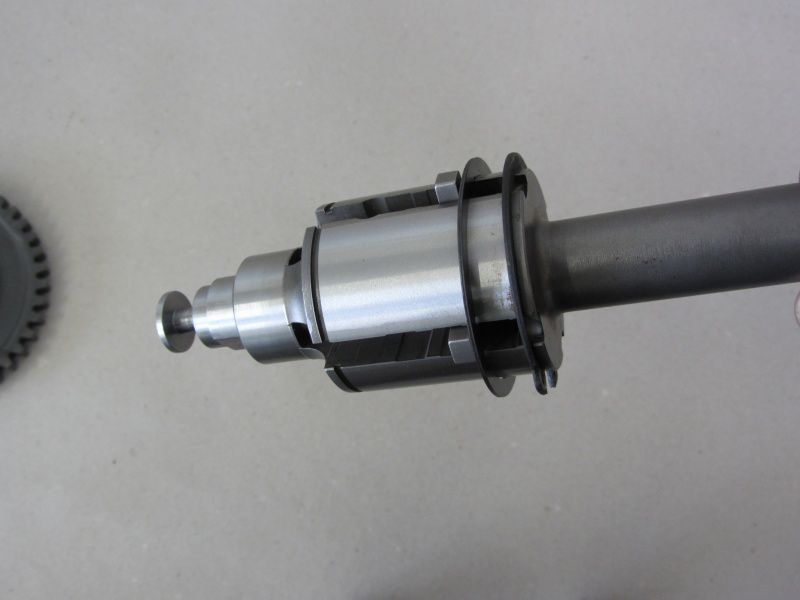
To complete the Christmas tree, the one is still missing axis, Warehouse and the Seeger ring.
The single ones Bearing needles are used later when installing in the motor housing.
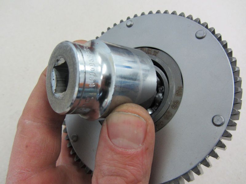
To install the 6302, we use a suitable nut which fits onto the outer ring of the bearing.
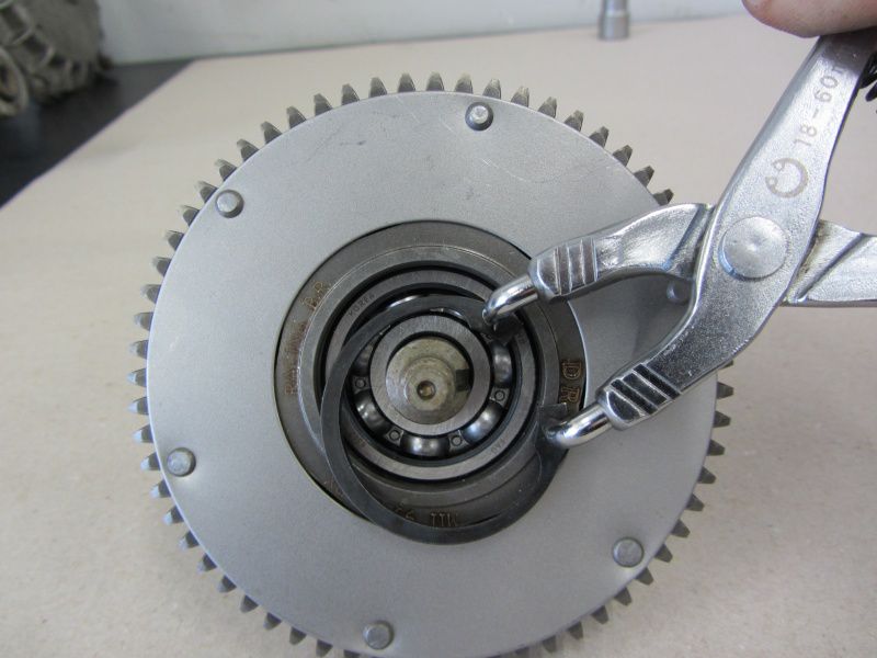
The whole game is then secured with a circlip.
The auxiliary shaft is ready for installation. Now we can Main shaft, turn to the partner on the output side.
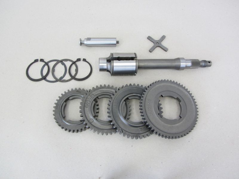
Up to the 4th gear of the Vespa T5 with 36 instead of 35 teeth, it is a standard PX200 gear.
The main shaft for the PX models from 1984 onwards have a special recess around the Switch cross use. 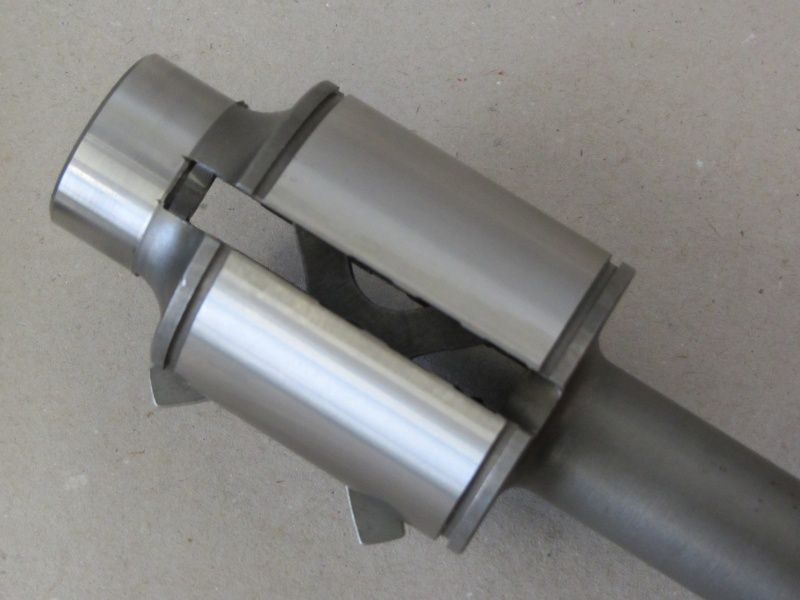
The switch cross can be turned into the correct position in this recess.
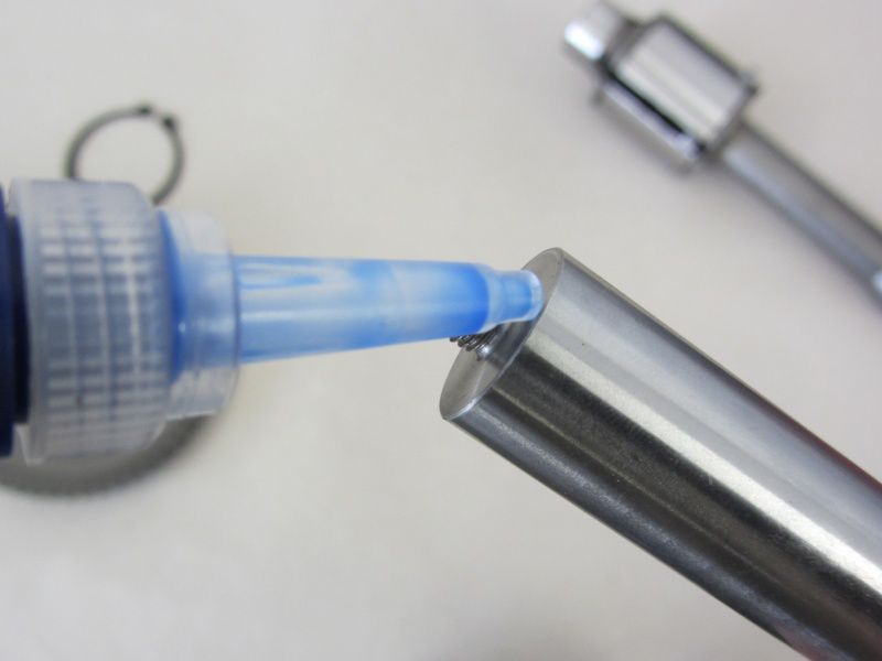
Next comes the Switch pin (Attention! Left-hand thread!).
With threadlocking secured against automatic loosening, the switch pin is tightened counterclockwise.
Now let's continue with the first one Seeger and shouldering a.
The 1. course runs with the flat side against this shoulder ring.
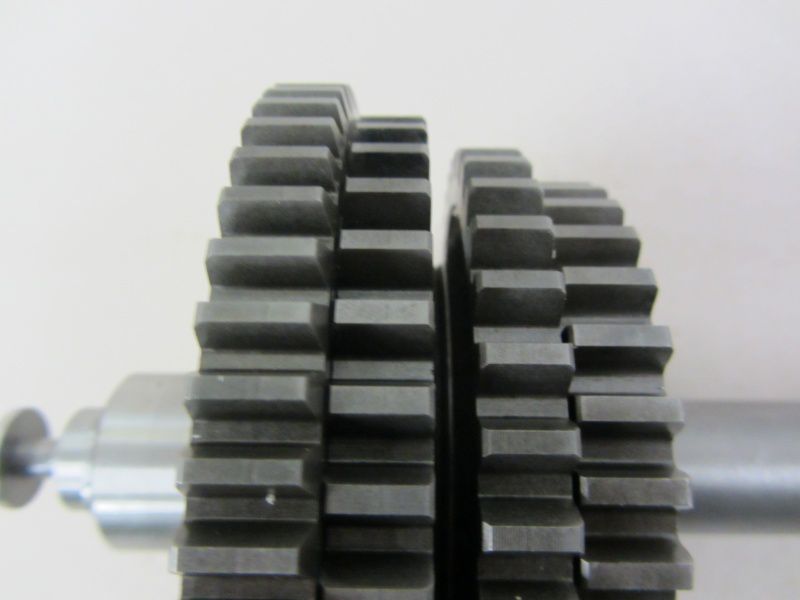
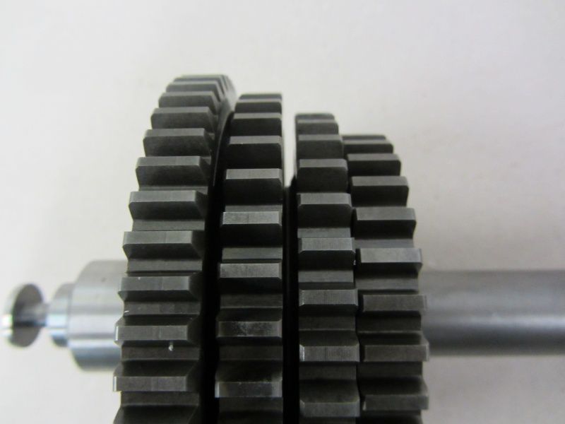
When assembling the gear wheels of gear 2 and 3, we have to pay attention to the correct installation position.
If the teeth touch the gear wheel in front of it, the position is NOT correct (picture below)
The positions are only correct when the gears 1-3 are clearly spaced apart.
The position of gear 4 is self-explanatory. Here, too, we find a contact surface for the shoulder ring.
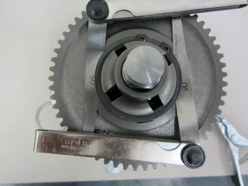
As soon as the last mentioned is mounted with the Seeger ring, we measure the play of the gear wheels on the main shaft.
Piaggio recommends an installation clearance between 0,15 and 0,40mm. In the case of a transmission that has already seen several kilometers, the lower installation dimension can be used.
In the case of a gearbox composed entirely of new parts, however, a somewhat tighter clearance is advisable, since all surfaces still have a high surface roughness and shrink more over the first few kilometers.
0,05mm is more than sufficient for a new gear package.
The main shaft is now also ready.
The only thing missing now is the clutch, one of the most important and most heavily stressed assemblies in the engine.
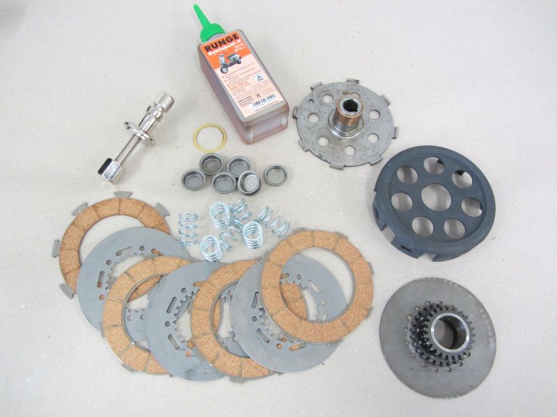
With regard to the straight toothed primary from Malossi, we use one CNC clutch basket from MMW. Together with one Pad set from Malossi can be used to create a durable package.
We sort spring plates and springs into the basket.
In the original clutch basket, as in the baseplate also, a hole for installation orientation.
The MMW basket does not have this hole, so we have to find the correct orientation of the base plate over the springs by repositioning it.
It doesn't fit like that, ..
so one more ...
That looks better.
With the Clutch compressor we now pretension the base plate against the springs.
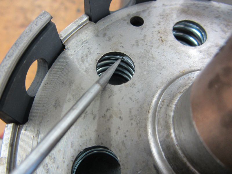
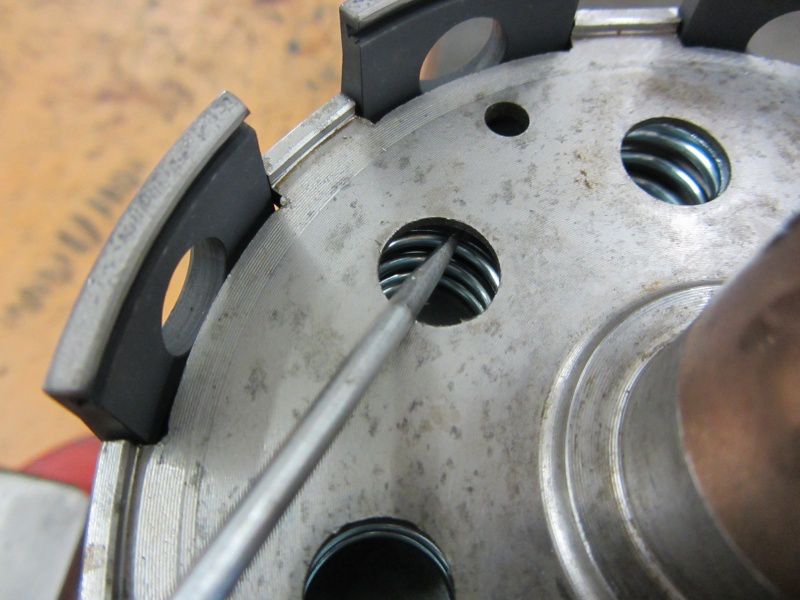
This shows very quickly which springs are not in the guide of the basic column.
With a screwdriver, the spring can be threaded into the guide easily and with an audible “click”.
When all springs are seated properly, the thrust washer for the pinion is installed.
The grease takes care of the first couple of revolutions of the clutch 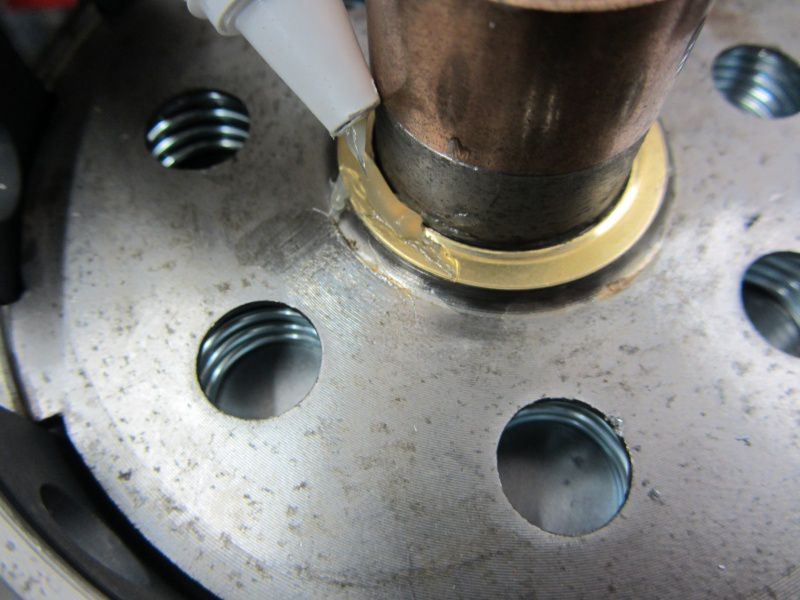 for lubrication.
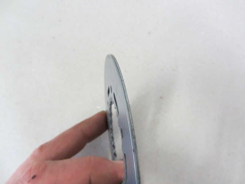
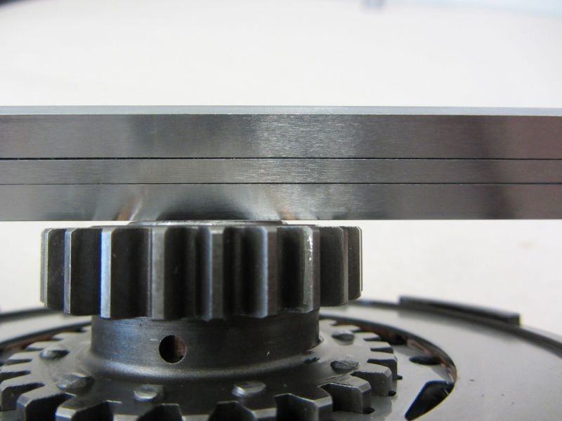
Before we now assemble the pinion and the lining disks, we first check the steel disks for distortion. By laying them on top of each other and twisting, you can tell whether a crooked dog has made it into our rubber set. However, everything is OK here.
In the case of wavy panes, you would see a gap that opens and closes when the panes are turned against each other.
Such deformed disks can extremely restrict the function of a clutch and lead to leaps and bounds when starting off with a lot of steam.
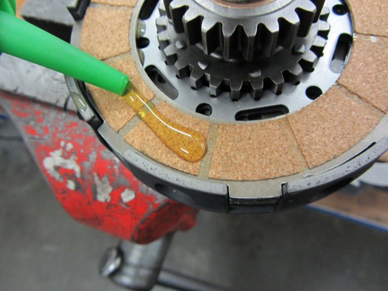
We use the toppings with oil.
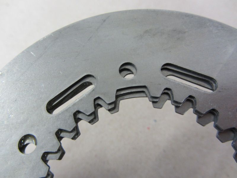
The steel disks also have an installation orientation, which can be easily recognized by a missing tooth. This orientation is necessary so that the recesses for the oil are exposed in all steel disks.
Now that we have alternately sorted the steel disc and the cork lining in the coupling, the whole story is provided with a locking ring.
Last but not least, we check the clearance on the clutch pinion. 4-5 / 10 should be present.
If the play is too small, it can lead to the clutch not disengaging properly and the shifting to work poorly, as there is always a load on the transmission despite the clutch being pulled.
Finally, a small function test:
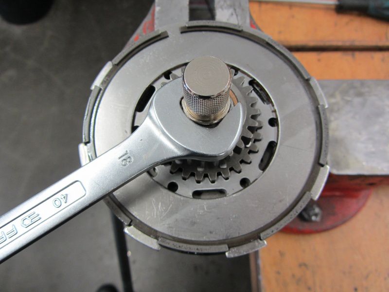
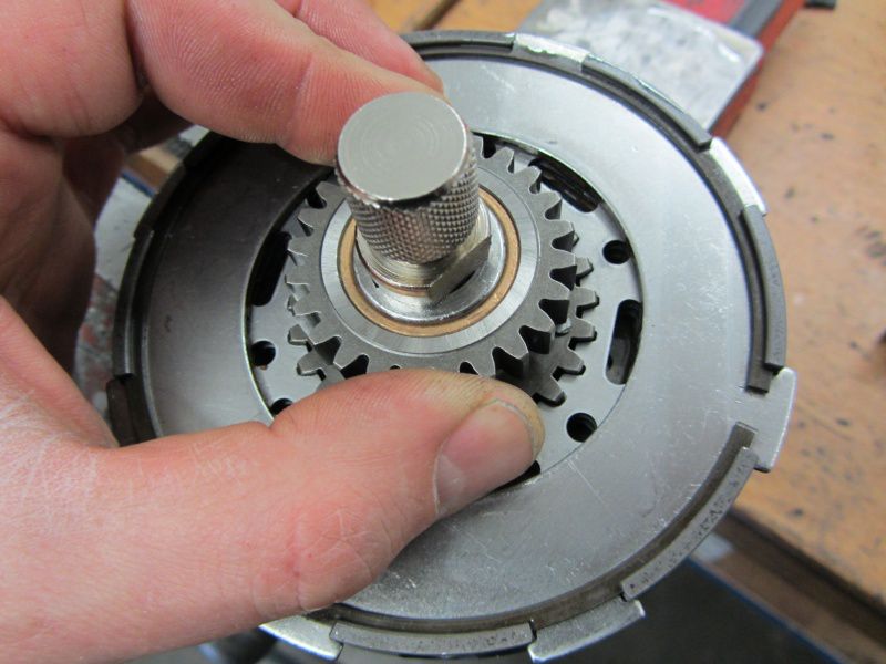
The clutch is pre-tensioned 2 revolutions with the clutch compressor. If you hold the basket, the pinion should now be relatively easy to turn by hand.
If there is sudden resistance at one or more points, the clutch must be dismantled again and the discs checked or ensure that all components are in place. The forgotten thrust washer, for example, would be the classic ...
After 1,5 to 2 turns with the key, the clutch pinion should be able to be turned by hand.
So much for today.
Tomorrow ball bearings and gears will go into the engine.



Leave a Reply
Want to join the discussion?Feel free to Contribute!