Project Racer - Wednesday 15.02.2012
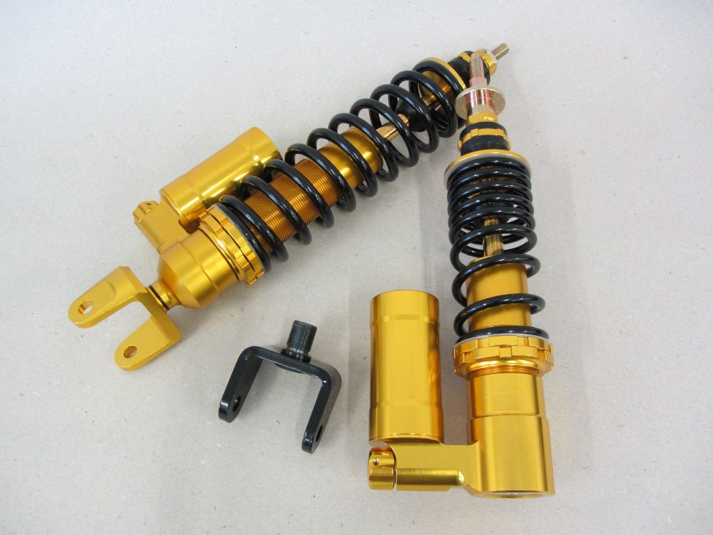
Before we continue with the ignition as promised today, there is first good news from Austria and on the subject of shock absorbers.
Finally the dampers for our project have arrived, of course changed visually to match our racer compared to the later series.
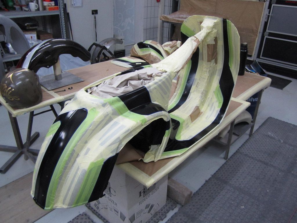
At the “Pfeili” work continues ...
But it is much better that the finished frame should be with us by Tuesday next week.
That would mean a full 2 days (we want to leave on Friday at 6:00 am!) For the assembly.
Now the ignition continues.
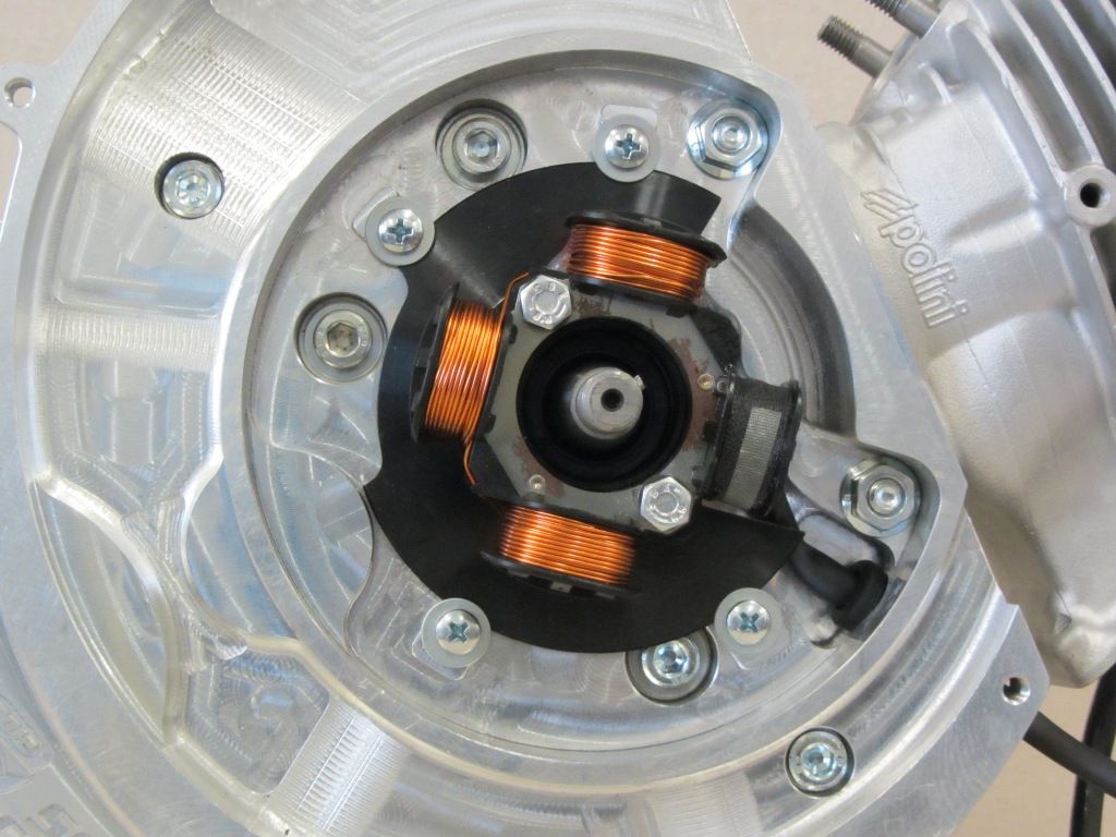
The base plate is screwed onto the motor housing in the Vespatronic basic setting.
Then we put the pole wheel on.
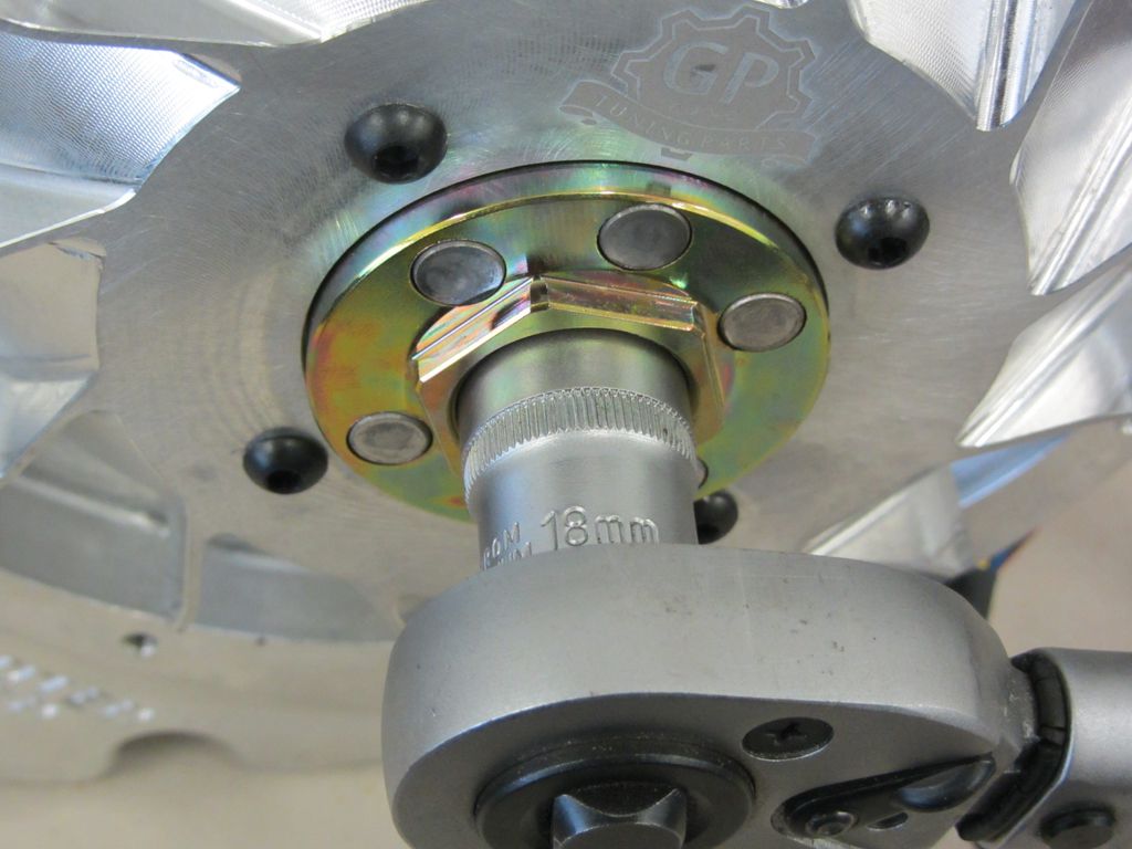
It is characteristic of Vespatronic that the normal Vespa flywheel nut can usually only be fitted with a nut that is turned off in diameter.
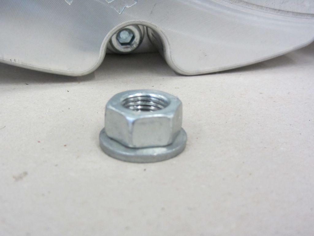
Or you can use a mother from the Piaggio automatic range.
Within the Vario nut for the large Piaggio engines, the wrench size is reduced to 18 mm.
In addition, the nut comes directly with the fuse pressed on.
A nut SW18 fits unchanged into the Vespatronic pole wheel.
The pole wheel is tightened to 65Nm.
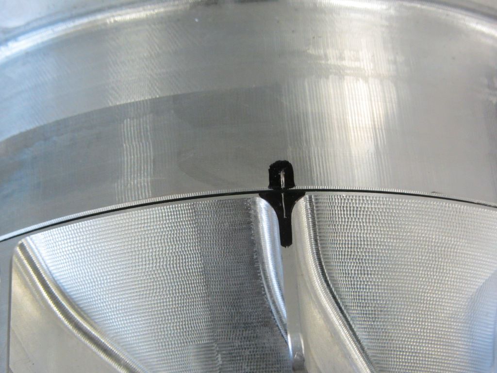
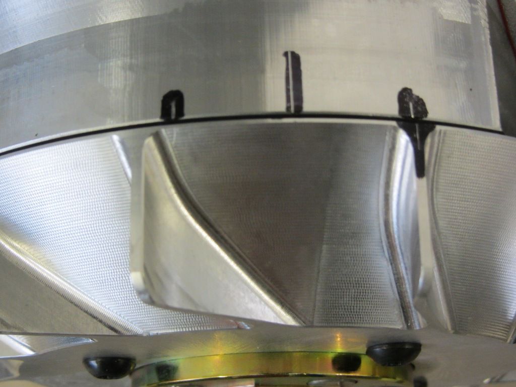
In order to check the ignition timing later and to make understandable changes, we still have to attach ignition markings.
We use the reversal measurement for this.
We apply the first marking with a piston stopper, which is to serve as a defined stop.
Mark 1
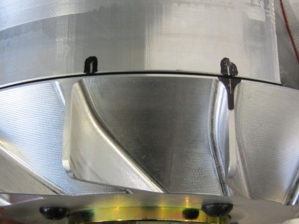
then over the UT again to the stop. Here you transfer the marking from the pole wheel back to the motor housing.
The OT is between these two markings, the easiest way to mark it with a compass.
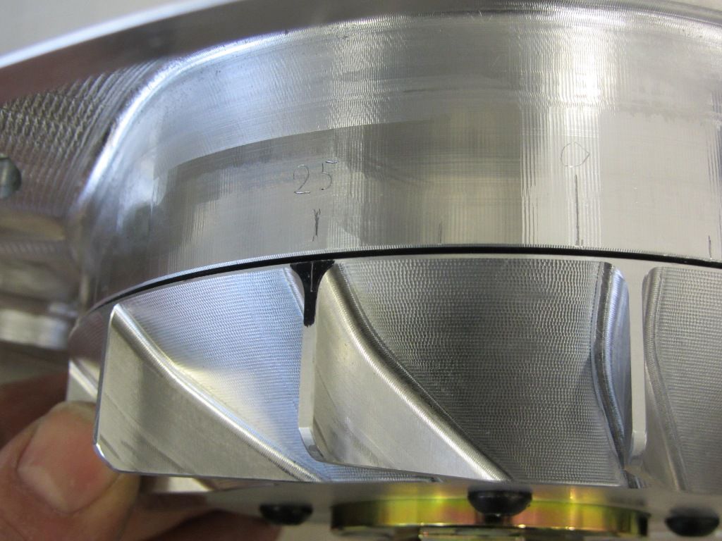
Now that we know the OT, the desired ignition markings can be applied counterclockwise.
To do this, you have to remove the circumference on the motor housing and divide it through 360 °.
The result then corresponds to the value in mm for 1 °. In our case we come to 1,36mm / 1 °.
The Vespatronic adjusts the ignition point with increasing engine speed by 8 ° in the direction of retardation, i.e. less degrees from TDC.
So if we want an ignition value of 17 ° before OT at our engine speed, the ignition must be set to 25 ° in the basic setting. In order to be able to control this, we put a mark at 25 ° BCE. With our determined value, we come to a radian dimension of 34mm, which we remove counterclockwise from the TDC.
A steel or a piece of tape measure is best.
Setting and labeling.
As soon as the engine is running, the setting can be checked with a strobe light.
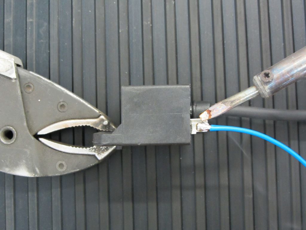
Briefly about the CDI, the Vespatronic CDI is notorious for getting rid of its plug connections every now and then.
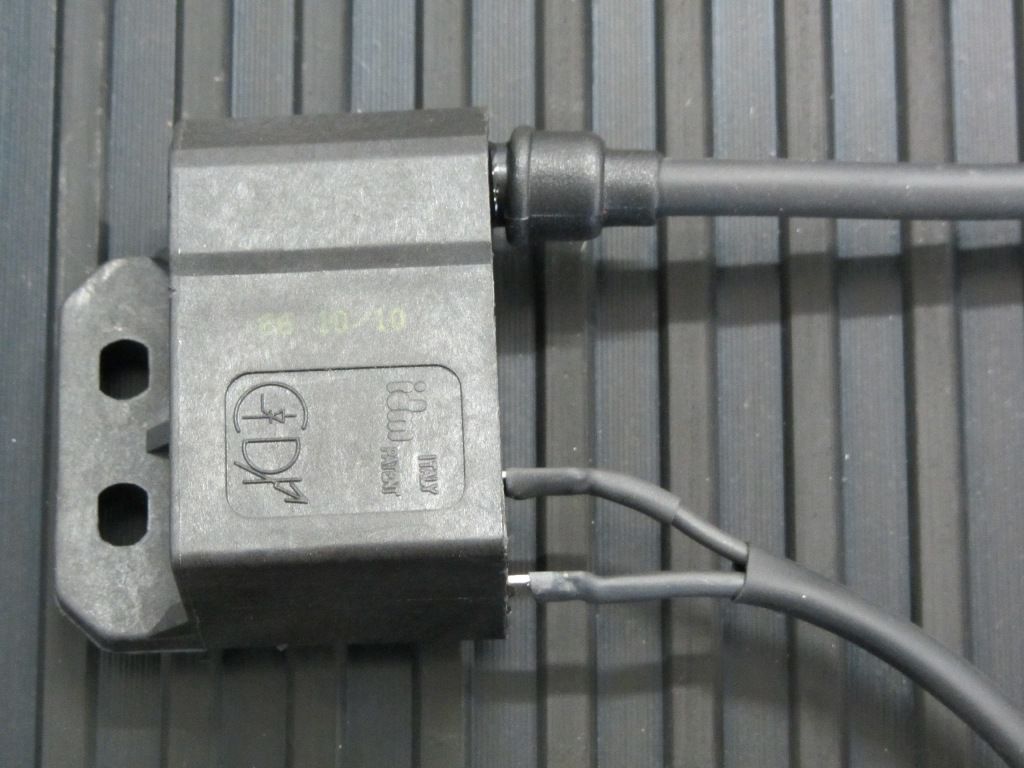
So that it doesn't get that far in the first place, we simply leave the plugs off at this point and solder the cables.
Polini, for example, offers one Similar ignition system on whose CDI the cables are already soldered on.
The soldered cables are still with shrink tubing Protected against vibration death before being together in one Bow pipe disappear.
So much for today….





Leave a Reply
Want to join the discussion?Feel free to Contribute!