Our test engine ran warm and the spraying with a secondary nozzle 48/160, air correction nozzle 160, mixing tube BE3 and a main nozzle of 140 seems to work for now. Now we can do the first runs to measure performance.
To do this, the overall ratio in 3rd gear is measured 2-3 times on the P4. In our case, the overall ratio is 3,21. We can re-enter this value manually in later runs in order to eliminate errors when measuring and to obtain consistent, reproducible results.
So we do the first 3 runs. If all runs are almost congruent, we can assume that the experiment worked well and that we “experienced” a comparable result.
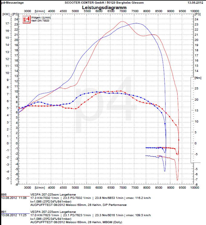
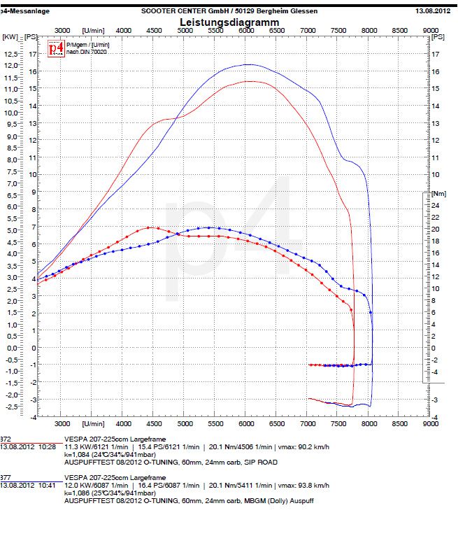
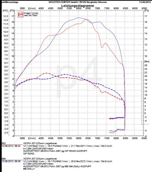
Here is the first result.

It's nice to see that, as expected, the engine makes a lot of torque available very early on. This impression is also confirmed during a test drive on the road. In terms of the tractor, the engine pushes off very nicely at 3500 rpm, i.e. practically at increased idling speed, with 17 Nm.
Besides, the unobtrusive suction noise of the Polini solution is pleasing. With the adapter, Polini has incorporated a small but important trick. The sound waves break effectively on the inner edge of the adapter and thus become a sonorous, inconspicuous suction noise.
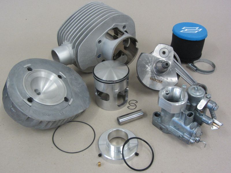
Back on the test bench, we mount the MMW cylinder head on our 210 Polini.
For the tests on the test bench, we put a 0,5mm and 0,2mm thick Polini cylinder head gasket under it so that we get a comparable squeeze dimension of 1,70mm. It is absolutely advisable not to underlay an O-ring sealed cylinder head with an additional gasket. The material of the solid seal could be pressed into the O-ring groove by the surface pressure in connection with the thermal load on the cylinder head, damage it and thus render it unusable.
For test purposes, however, this is possible without any problems, after all we are not planning a circumnavigation of the world but a series of tests. Should the shape of the combustion chamber of the MMW cylinder head prove to be useful, we can think about a necessary change at this point.
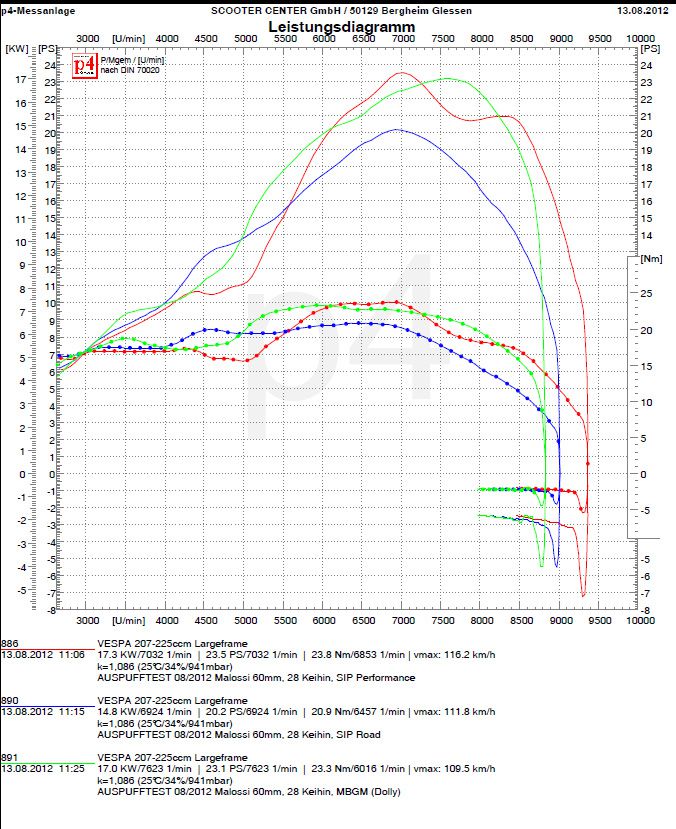
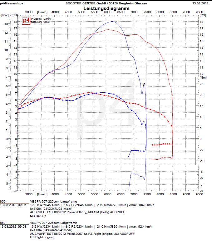
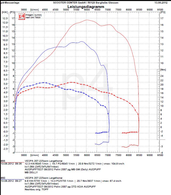
After 3 more runs we get the following nice, colorful mountain range in direct comparison.

RED: MMW

BLUE: Worb5

The extra power of the MMW cylinder head results on the one hand from the slightly higher compression and most likely from the different combustion chamber geometry compared to the Worb5 cylinder head. Since we both brought the cylinder heads designed for a 57mm stroke to the same crush dimension of 1,7mm, one can speak of a fair comparison here.
The maximum torque is as usual at 4700rpm and increases with the MMW cylinder head to a whopping 22Nm.
At 7000rpm there are still 17PS and 17Nm. Certainly good to achieve an average high travel speed.
We save ourselves the experiment with the MMW cylinder head for 60mm stroke. Not out of laziness, but because we already know that the engine responds positively to a little more compression.
Because with the same combustion chamber geometry, but with the compression reduced due to the larger crush dimension, no increase in output or torque is to be expected.
A little more band with higher torque and more power in the higher speed range would be desirable. This would enable us to better overcome the exponentially growing driving resistance with increasing speed.
Mmmmh, what else could you try now? Actually already suffering at a high level? After all, we are talking about an engine which, thanks to its well-considered selection of components and its assembly, provides quite a remarkable performance.
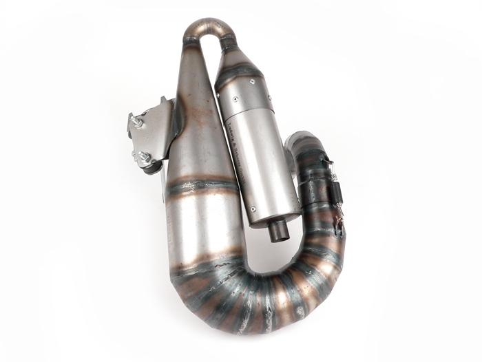
With a look through the test stand room, we discover our test prototype of the bgm bigbox -

we should still try that.

Tomorrow… (:

Only a few more steps separate us from hooking the engine into a test vehicle.

As a test victim for our Polini engine, we use the familiar one Silver Fern .
When assembling the pole wheel, make sure that the groove is the Crescent wedge hits exactly.

Then the Flywheel nut tightened with 65Nm. washer do not forget !

The rear one brake drum is initially only attached and fixed with the nut.

As soon as the rear brake is functional, the brake drum can be attached with 110Nm. Fuse cage and split pin must of course not be missing.

We still connect the controls on the handlebars to the engine, that is Gas-, switching and Clutch will attached and adjusted.

The security game on clutch lever should be between 1,5mm and 2mm in order to avoid the clutch cable being actuated when shifting into higher gears and thus the Pressure mushroom on the pressure plate works and the Clutch possibly even actuated.

Olive oil and fuel hose follow. The air bubble in the oil hose is intentional. When connecting for the first time, you can check whether the oil is being pumped into the carburettor.

However, the air bubble should not be larger than shown here, otherwise there is a risk that the pump will run empty and no more oil will be transported towards the carburetor.

For the “first firing” we fill the tank with 1 liter of super in a mixture of 1:50. This amount of fuel should be enough to bridge the gap until the oil pump delivers the valuable lubricant.

The last missing parts are the Flywheel and the Cylinder hood.

Then it's fire free!

After warming up for a few minutes, we first shift through all gears once and test whether all gears hold and the clutch disengages properly.

A quick look at the oil hose reveals - the pump is running.

So then, first attempt on the test bench with the following setup:

- Polini 210, Outlet, piston and overflow channels are not machined, Spacer cylinder base 1mm.

-YES 26, Cosa float chamber ceilingl with additional bore, nozzle holder also with additional bore

- Nozzles 48/160 - 160-BE3-a set Main jets to play around

-Inlet area freed from the disturbing edges, the seals adapted to the new contour. Polini velocity stacks with adapter and Polini air filter.

-bgm-Pro 60mm crankshaft

-SIP Road exhaust

- Ignition 18 ° bc

-Cylinder head Worb5

To be on the safe side, we check them Ignition adjustment by reversal measurement. If the tolerances on the crankshaft, pole wheel and base plate are correct, the markings should be on top of each other when flashing. This time we made the 18 ° marking on the pole wheel.

Ok, the ignition is correct - then nothing stands in the way of the first test run ...

Now it starts with measuring the timing and the final steps before the first test bench runs.

With a 1mm Cylinder base gasket tells us that Degree disc an overflow angle of 125 ° and an outlet angle of 172 °.

Values ​​with which you should definitely try a few times.

We also try out 3 different cylinder heads.

MMW for 57 mm and 60 mm Hub and one wrob 5 Cylinder head for 57mm stroke.

At first we only consider the squeeze dimension. The MMW head for 57mm stroke is, as expected, a bit tight at 1,0mm, a test with an additional cylinder head gasket from 0,5 mm or 0,8 mm is still possible. The head for 60mm stroke is practically designed as a head gasket variant and compensates for the stroke difference of 1,5mm through the combustion chamber, so the squeeze dimension here is, as expected, quite high at 2,7mm.

However, the MMW cylinder head for 60mm stroke also leaves the scope to lower the cylinder again. This shortens all steering angles, but this results in more foresight, which could perhaps have a positive effect on driving behavior.

The cylinder head from Worb5 was also made for a 57mm stroke, as is well known, the squeeze dimension on 57mm stroke with this head is quite large. In our case, this results in a quite usable squeeze dimension of 60mm with a 1,7mm stroke without an additional cylinder head gasket.

To what extent the different combustion chamber geometries then affect the power delivery, we will determine on our test bench.

The assembly of the carburetor is also part of completing the engine.

Obviously a fairly trivial topic, but you can skilfully screw it wrong here too.

Friends of the generous use of sealant should exercise caution. The channel on the underside of the carburetor pan and the oil hole in the carburetor (marked in red here) must remain free on engines with separate lubrication. If the supply routes are closed, the crankshaft, alternator bearings and cylinders run without oil; and usually not for long '.

The frugal SI carburetor itself is very sensitive to incorrect attachment.

If you overdo it when tightening the screws, you could later struggle with a jammed slide. All newer SI carburettors have already been improved so that the screw head can no longer act directly on the slide guide.

To be recognized by a small undercut. This trick can also be applied to the older carburettors.

But even in spite of this preventive measure, you should stick to the torque of 16-18Nm when tightening the screws alternately.

There are 2 variants of the carburetor attachment that can be used.

The “old” version with studs and sleeve nuts exists since Largeframes were equipped with SI carburetors there. The newer variant with a Set screw only came up with the Lusso or better the models with separate lubrication.

The reason for this is simply the ease of installation. Carburettors with separate lubrication are noticeably long due to better accessibility Mixture adjustment screw and an Push rod to hook in equipped. For use on engines with mixed lubrication, the pull bar can also be easily exchanged. Before the carburetor in his tub Taking a stand, we cut the mixture adjustment screw with a file. This will make it easier to set up later.

Shit, besides ...

That happens often and with pleasure.

When inserting the carburetor, make sure that the hook catches the tab of the oil pump.

If the carburettor is screwed tight as shown in the picture below, on the one hand the slide rod will be damaged and on the other hand, the carburetor would have been successfully disabled.

Stud bolts for attaching the carburettor would be a hindrance when inserting, so Piaggio came up with the idea of ​​the set screws. Unfortunately, there is a small risk in simplifying it.

The screw at the rear in the direction of travel sits directly above the rotary valve surface.

At this point we forget the required one slices or Snap ring to use, the rotary valve will inevitably be damaged.

The carburetor is attached in steps of 8, 12, 16Nm.

The Polini funnel is only fixed with a screw. the Idle speed screw is only used for installation orientation, as the funnel has a through-hole at this point.

For the test stand, we are content with simply attaching the single screw due to the expected nozzle change. However, as soon as a suitable carburetor setting has been found,
you should get the screw with threadlocking fix.

The Ignition stator For the first test runs we set it to the “IT” marking, i.e. an ignition point of 18 ° before the end of the day.

With the appearance of the new Polini Evolution cylinder, the well-known Polini gray cast iron cylinder also received an upgrade and from now on has the addition "Racing" in the designation. A really massive cylinder head with an enlarged cooling surface, CNC machined combustion chamber and a copper gasket.

Due to the greatly increased material thickness and the use of a head gasket as in the Evolution cylinders, leaks on the cylinder head - provided that it is correctly installed - are a thing of the past from now on.

Fortunately, Polini offers the new one Racing cylinder head also available as a spare part that can be adapted to any “old” Polini. The ones required for assembly longer cylinder studs To attach the stronger cylinder head, a cylinder head gasket is included in the scope of delivery. We recommend this for screwing M7 nuts from Naraku.

Due to the increased cooling capacity, Polini has given the new racing cylinder head a little more compression.

We measured the difference for you with a burette.

Compared to its predecessor with 16,8ccm combustion chamber volume, the new cylinder head comes with a combustion chamber volume of 15,9ccm and thus increases the geometric compression from 8,7: 1 to 9,1: 1.

We simulated the volume of the cylinder head gasket by measuring it with grease.

The subtly increased compression, paired with the more modern shape of the combustion chamber, help the Polini gray cast iron to achieve more torque and power without the cylinder head being subjected to thermal overload. Of course, this only applies if the motor is set correctly. Of course, the new cylinder head does not iron out incorrect carburetor and ignition settings.

To be on the safe side, you should re-determine the pinch dimension after assembly and adjust the ignition timing depending on the engine setup. With increased compression it may be necessary to select the ignition point a little later (i.e. fewer degrees before TDC).

The new Polini cylinder head is also interesting for class 5 of the ESC, as it has been approved in class 2012a since 5.

The carburetor and intake area are prepared.

Now we can fill the engine with the parts we still need.

The 4 speed levels are in the form of a Px200 transmission built-in.

Switch cross and gear wheels are mounted accordingly.

The switch cross should be something threadlocking . use

Gear wheels, Seeger and Shoulder rings can then then be draped to create a pretty overall picture.

The play of the gear wheels should be in the range of 0,05mm-0,15mm during installation. It is best to control the existing game with 2 Feeler gauges. With new shoulder rings you can choose the game tighter, since the bearing surfaces of the shoulder rings shrink even more over the first few kilometers than with already used shoulder rings.

The crankshaft still gets even with that suitable tool missed the inner ring of the alternator bearing.

And the Ball bearing set implanted.

The ball bearings are with Cooler spray cooled and gently brought into your bearing seats by heating the housing halves.

Exceptions are the two needle bearings in the “small” half of the alternator housing.

The Alternator bearings should be safe with the matching tool be guided.

The B188Bearings for the main shaft have to be given a little extra, 1000gr. in shape a hammer should be enough as gentle intercession.

Once all the bearings have found their place, they will Shaft seals assembled and puzzles with the Needles of spurious consequences. The individual needles with fat fixing helps a lot. You should still have a steady hand. Don't forget to count, 21 needles should work here.

Kick starter pinion and segment are the last missing components.

Do not forget! the Pressure spring the kickstarter sprocket is best glued in with grease.

The crankshaft is installed and the housing assembled.

With the torque wrench, everyone will Housing bolt evenly tightened.

The oil pump drive is installed.

The Worm wheel is from 2 Thrust washers flanked. The one is missing in the picture below Seeger ring serves to secure the worm wheel.

Nachdem die Oil pump shaft mounted with a little oil can do that pinion placed on the crankshaft and mounted the clutch. Most crankshafts have a small radius towards the coupling stub on the coupling side. Therefore, the bevel of the pinion should point towards the crankshaft during assembly.

Here in the installed state you can see how nicely the dust lip on the wider sealing surface of the bgm crankshaft protects the actual sealing lip.

The most important link between the gearbox and the crank drive is the clutch.

Therefore we rely on the tried and tested bgm Superstrong clutch.

Designed for 10 springs, the Superstrong offers a lot of possibilities to vary the spring stiffness.

In our case we are using 10 XL feathers.

Dhe shaft-toothed hub is used with oil.

Clutch pinion and Topping packt with steel discs consequences.

When installing the pads for the first time, you should add a little oil.

With the steel disks you have to pay attention to the positioning of the Washer with the notches respect, think highly of.

This is deliberately deformed by a few 1/10 mm in order to immediately create the clearance when the clutch is actuated so that the clutch separates cleanly.

Is the topping package and the Locking ring mounted, the coupling is ready for installation.

By the way, all complete bgm-Superstrong couplings are pre-assembled for you in exactly this way. Including adjustment of the clearance and control of the freedom of movement.

The self-locking Collar nut we fastened with 60Nm.

Now that the engine has been put together so far, the cylinder can be attached for testing purposes to measure the control angle. Nice job for tomorrow :-)

Also the Polini velocity stacks and Dell Orto SI 26 let's take a closer look. Why do you need this funnel anyway?

In the end it simply helps the carburetor to suck in more air and to ensure a better filling with fresh gases. More ignitable fresh gases in the cylinder ensure more available power.

A larger volume of air must of course also be fed with more fuel. That's why Polini has already put one in the intake trumpet for the 200 engines 138 main jet at.

There is also an undercut in the funnel in the area above the auxiliary and air nozzle. This fulfills the task of supplying air, similar to the effect of drilling open the original SI filter base arises and helps the carburetor to a significantly better tunability and throttle response.

Since the actual air filter is no longer required by using the Polini funnel, Polini has come up with a clever solution.

An air filter is mounted on an adapter for the carburetor pan.

When assembling the adapter ring you should make sure that you have all the grub screws of the adapter, as well as all necessary connections on the carburetor pan for Gas- and Choke cable as well as the connection for the Oil hose which can achieve separate lubrication.

The fact that Polini has already included a 138 main nozzle in the funnel set gives an idea of ​​how much the air throughput could be increased. From a main nozzle size of approx. 130 you should take some precautions with the SI carburettor to keep the fuel supply constant.

First of all, a continuity test of the fuel tap should be on the program. For performance-oriented engines, the fuel tap should provide a flow rate of at least 280-300ml / min. Most standard petrol taps fail in this discipline, our remedy is here Faster Flow fuel tap.

Except for a well-functioning tank ventilation in the filler cap, can no longer be optimized in the tank area.

In the carburetor itself, however, there are also other bottlenecks which can have an unpleasant effect on the fuel balance.

The small float chamber of the SI carburetor must be constantly supplied with petrol under full load.

Unfortunately, the energy-giving juice must first pass through the eye of the needle "float needle valve".

The best way to do this is to swap it Float chamber cover against the variant of the Cosa carburetor .

On the right the normal SI cover, on the left the Cosa version.

In addition to the larger float needle, the valve bore and the needle seat are also made significantly larger.

We are also increasing the inlet to the float needle valve to 3mm.

Now we have done everything so that the float chamber is full of juice in every driving situation.

However, the carburetor still has a hidden bottleneck in store for us.

The inlet from the float chamber to the nozzle assembly.

The fuel must rush to the main jet as quickly as possible through the tiny hole in the center of the picture.

The crux of the matter here is that the bore is too small at 1,5mm from a certain main nozzle area. Approximately comparable to a 150 main jet. In order to ensure free travel here, the channel is drilled to 2mm. The hole on the left is only used to feed the choke system and does not require any further attention.

With the appearance of the Polini 210, a dream has come true for many scooter riders.

Proven Polini torque in an aluminum dress from the speed basement with little effort. On the first "test engine" with a stroke of 57mm, this assumption was consistently confirmed.

Polini has recently started offering other interesting toys to increase performance and, above all, to increase driving pleasure. In addition to the already available Intake funnel for the original SI carburetor, Polini announced the appearance of a new cylinder specially designed for a 60mm stroke along with a matching 60mm stroke crankshaft, so a Polini 221.

Inspired by these developments, we decided to build a complete engine for test purposes. First with the 210 Polini, this will give way to the big brother that will hopefully be available soon.

So we first drag the following toys to our test stand, or first of all to the workshop for assembly.

Cylinder kit Polini 210, cylinder head MMW and Worb5, intake manifold Polini for SI carburetor, 26mm SI carburetor and a crankshaft bgm PRO 60mm stroke.

We take a closer look at all parts and prepare everything for installation.

First consideration is the motor housing, this is where all the toys will move in later.

New PX200 motor housings are currently only available from Malossi. Except for the distribution channel, nothing has changed on the motor housing.

We pay special attention to the rotary valve inlet. In order not to obstruct the fast-flowing fresh gases there too much, we remove the factory-made burrs and edges. Furthermore, the inlet will not be revised.

At the heart of the engine, we use the tried and tested BGM crankshaft. Optimal intake control angles will help our test engine run smoothly over a wide speed range.

The BGM crankshaft also offers the option of installing an FPM shaft sealing ring with a dust lip on the alternator side thanks to a larger sealing surface on the alternator cone. Compared to the usual shaft seals made of NBR, the FPM shaft seals a significantly higher shelf life.

Next, let's look at the “Polini Funnel” ...

Ludwig & Scherer are THE two-stroke exhaust gurus! Especially with the Smallframeengine, one big hit chases the next. The official debut, the Hammmerzombie, is our long-running favorite Smallframe to fire. the "Big Bertha" has been specially developed for the Parmakit SP09 cylinders. With a nice wide speed range, the engine turns freely and the 20 HP + are easily cracked. the "Franz" is currently considered state-of-the-art when it comes to maximum performance at a wide speed range. The exhaust runs best at exhaust times around 190-185 °. With a machined Polini 133, 54 mm bgm shaft, Vespatronic ignition and 30 mm Mikuni carburetor (HD 290, needle 5EN68, ND 20) our Alex achieved 27 HP on the rear wheel on our test bench.

At the last minute our Alex reached the "Fire magic" Exhaust. In direct comparison to Franz, it starts a little later, but peaks significantly higher and makes a band that is 1.000 rpm wider. 29 PS on the gray cast iron Polini are an announcement. The recommendation for the timing is 126 ° for the transfer ports and 190-192 ° exhaust time. Processing quality, brackets, dampers and fit leave nothing to be desired! The plants are there for Chassis with as well as for Chassis without luggage compartment on the left.

Vespa BigBox Vespa exhaust

Development of a new Vespa exhaust system - the Vespa BigBox from Scooter Center

After we and Mark have brought the Lambretta BIG BOX so far that we can only wait for the manufacturer and, at most, issue reminders, we sent a few sets of PX exhaust shells to Doncaster.

Mark has all of his ideas regarding PX BIG BOX implemented directly after the Eurolambretta. On Monday morning the PX 200 BIG BOX was finally here in the store. A few minutes later the test bench computer started and the games could begin.

Vespa exhaust big box test

It was tested on:

Buy Vespa BigBox here


Vespa exhaust performance charts

Here is a small selection of diagrams. Uwe did a lot more runs that we will post over the next few days.

After our youngest had thundered “performance” on the test bench yesterday, we will carry out a few more tests today.

Therefore, today we take care of the carburetor adjustment and the optimization of the drive.

Contrary to the diagram you saw yesterday, the CVK carburetor implanted a 104 main nozzle instead of a 106.

In the area of ​​the drive we have that Weights on 15,5g in the Malossi Multivar increased and the originals Piaggio 125 clutch with red Malossi clutch springs equipped.

Since 4-stroke engines usually have a much wider band than 2-stroke engines, the idea behind it is that the power, which is already available at lower speeds together with more torque, can be used over a larger speed range and thus achieve a little more top speed .

Compared:

The red curve shows the first litter.

With a speed increase of 9500 rpm at 10-20Km / h, the driving behavior seemed very rough.
The working speed of the variator is somewhat high at around 9000 rpm, as there is still very little torque at this speed. Due to the somewhat too rich carburetor setting, it stopped at approx. 110Km / h.

Green curve:

After a few attempts, heavier weights of 15,5 grams will come here. and harder clutch springs (Malossi red) are used. The speed start is significantly lower at 7500 rpm and the engine provides significantly more torque at this speed. Easy to read from the steeper increase in output up to 30Km / h. Due to the lean carburetor setting, the engine now turns out more freely and, coupled with the lower speed level, it can be turned out quickly at higher speeds of over 130Km / h.

Blue curve:

Practically everything like the green curve, but for the acoustics lover without a DB killer ... :-)
The volume limiter swallows a few percent of the valuable work done, but fortunately little.

Well done!

As a guest on our test bench, our employee Manuel with his Derbi GP1 125 @ 280ccm and a very powerful engine concept.

Even if the unobtrusive appearance of the GP1 brings tears to your eyes, the very powerful engine immediately puts a smile on the driver's face.
When the engine set up on this project began, Malossi probably only just got one Cylinders for the 300 engines thought about.

Therefore one serves here KB-Racing crankshaft with 63mm stroke from the 300 motors as the basis for one 270cc Malossi cylinder, which was actually intended for the smaller 250 engines.

So that the crankshaft and the piston can enter into a connection, the piston from the Malossi kit had to be provided with a 16mm piston pin bore.

The 270 cylinder from Malossi comes from the factory with a rather, well, cautious squeeze dimension.

Therefore, the cylinder only had to be underlaid with a 3mm thick base seal despite the 0,8mm stroke extension.

With the 4-stroke, most of it is a matter of the head, in the truest sense of the word.
What is with the well-known 2-stroke channel areas and control angle, is with the 4-stroke valve area and camshaft lift.

Especially the 250 and 300 engines from the Piaggio range suffer, in terms of performance, from the very throttled cylinder head that the Piaggio modular system uses from 125 to 300ccm.

Just replacing the factory throttle with the Malossi V4 head would already help many a GTS250 / 300 to run more smoothly and to get plenty of torque.

You can tighten the 300ccm dish even further with a Malossi camshaft.

For comparison,

a Vespa GTS300 is specified by Piaggio with 22PS - on the crankshaft.
After all horses have run through the drive and gearbox, an average of 19 of them arrive at the rear wheel.

Our test bench diagram also shows the rear wheel performance of Manuel's GP1 ...

A very good result for the first litter. Maybe even with a few modifications to the Air Filter and Power Type still some achievement can be found.
A longer gearbox couldn't harm the GP1, with the original 125 gear ratio, Vmax is achieved at 110Km / h. Sufficient power to clearly penetrate into the range of 150Km / h is definitely available.
A pair of Malossi Torque Drive has already been installed. Faster throttle response from narrower corners and better acceleration result from this measure - an effect that can only be experienced on the road and that no test bench diagram reflects - so GOOD RIDE!

Today a very nice Rally 200 was presented on our test bench.

The project to get an everyday tractor engine was well met here.

A serves as the basis PX200 motor, the rotary valve in the housing has been subtly expanded for more inlet angles before TDC. An original Piaggio comes as the crankshaft PX200 shaft used that was not processed.

The new 210 Polini will have a SI26 carburetor with Polini velocity stacks ventilated.

By the Polini velocity stacks the available torque increases very clearly in the lower speed range. For a comparable engine with Malossi cylinder Without the Polini funnel, almost 4Nm are “missing” in the same speed range!

On the outlet side, the Alu-Polini is fed by a SIP Road Exhaust supports.

From idle speed, there is a lot of torque and power.

18PS at 6000rpm and 23Nm from 4500rpm speak a clear language.

With a long Primary translation the torque, which is practically in abundance, can be stretched and high speeds can be achieved at relatively low speeds.

Very nice device!

The ESC season is just around the corner and with it the preparations. This year we will see new engines and vehicles on the racetracks in Germany, France, Austria and Hungary.

A typical K1 engine has appeared on our test bench and is checked for its performance and functionality.

The ESC rules accordingly, the stroke is limited to 51mm.
Hence in this case one comes BGM crankshaft with 51mm stroke and 105mm connecting rods are used.

The one enthroned on the case Polini Evo is from one, with 0,35mm carbon material converted to 2 flaps Polini membrane with Strohspeed intake manifold ventilated. For the mixture preparation there is a 33 Keihin responsible. To keep the crankcase clean, the air is passed through a Marchald air filter sucked in. The very good air throughput of the Marchald filter and the resulting very low power dissipation in the per mille range make this filter, which has been tried and tested on the road, also interesting for racing use.
Ignition is via Vespatronic, which is set to 24-16.

On the outlet side, the K1 will be represented by one French charged.
Good torque values ​​and moderate speeds make this exhaust very interesting for the circuit.

The power generated is currently still on a reinforced XL2 coupling DRT Runner countershaft transferred, but more on that in a moment. Now first curve discussion:

All in all a typical Franz engine, Reso entry between 5500 and 6000 rpm, peak at around 9000 rpm and funny overrev up to 10.000 rpm.

With 11PS at 6000 rpm in the ascent it is also quite pleasant to drive.

With over 20 hp from 7300 rpm to approx. 9700 rpm, you can always move in the power range if necessary thanks to the Runner auxiliary shaft.

Now comes the crux of the matter, the clutch apparently disengages at the torque applied here, at almost 20Nm it's simply over. That means in plain language, the engine is opened again and it becomes a Hartz4 coupling installed.

Perhaps then something will change in terms of power and torque.

Even if the performance does not increase any further due to a clutch that does not slip, at least wear is stopped. A slipping clutch is likely to burn within a few laps on the racetrack or on the road after a trip in the country and can also result in consequential damage.

Maybe we can still find time to make a portmap of the cylinder.

Yesterday our friend Ercole was with us again with his Lambretta D Racer. You can find the blog entry about his first visit with us here. His racer was tuned for the Cologne circuit on the Nürburgring so that nothing stands in the way of the race.

Setup has changed as follows compared to his first visit: 30 series VSH carburetor

The blue curve shows yesterday's test run and the red curve from his first visit a year ago. 1HP more power and better torque were the end result. That Scooter Center Team wishes good luck on the Cologne circuit.

Thomas from Aachen visited us with a rather bizarre conversion concept on his Smallframe Engine.

In here comes from the Malossi program 172cc cylinder used, which is actually intended for the Piaggio automatic models TPH and SKR.
With some effort, Thomas was able to put the cylinder on a Vespa Smallframe Adjust the motor housing.

You can find more detailed information on this in the GSF

Some of these individual projects bring about rather dubious "improvements for the worse".

In the case of Thomas' engine, however, one can speak of a very suitable conversion.

In comparison, you can see an early one in the diagram VSP and a typical Smallframe Exhaust, the Franz.

All in all, these are extremely good values ​​that are sure to be easy to move on the road. It doesn't always have to be the Ü30PS, the corresponding torque also makes you fast, fast.

The fourth Aachen roll-up started on Saturday. The official pictures are there here.

We took this opportunity and are with ours Silver Fern been there. So that we could properly test our project. With arrival and departure and the tour, it was almost 200km that were covered without any problems. A stable touring engine with a lot of torque and power.

From the weather, everything was really there. Got into some heavy showers on the way there. Then at the meeting point in Aachen it shook heavily again and even hailed lightly. The first half of the route was driving through pouring rain.

After the break, Peter had mercy on us and we were rewarded with sunshine. So the final grilling could be enjoyed properly.

Conclusion: A great event and we all hope for the Classic Day on May 5.5th. to see in Glessen.

Installation of Vespatronic ignition

The Installation of the Vespatronic requires real interpretation work on the subject of electrics.

To make matters worse, the fact that the currently enclosed connection diagram is not correct.

Here you will find the Vespatronig and a large selection of Vespa ignitions

If you were to believe the circuit diagram, you would simply have to put the mass and excitation voltage together and then redistribute them to connections 1 and 2 of the CDI.

From the ignition base plate, it is of course correct to connect red / black to -1- (the wider slot), again connected to green of the wiring harness and blue to -2- (the narrower slot), connected to black of the wiring harness.

There is a great risk of confusion in the cable box, where different colors have to be brought together. We have provided all cables on which there is voltage when the plug-in connections are loosened and the engine is running. The ground connection does not pose a potential danger and can be equipped with a plug.

So that one does not confuse the two cable connections excitation voltage and on-board network, which are each equipped with a plug-in sleeve, one can memorize “blue sea under yellow sun” - well - in practice it works ...

We place the ignition base plate on the later of the two markings as a test.

As soon as we have put all the glory in the cable box and the pole wheel is reassembled, we start the engine to check the ignition timing.

We have already determined and drawn the markings for the OT and from OT 25 ° beforehand by means of a reversal measurement.

Flashed off briefly.

The ignition is at 25 ° at 2000 rpm-1, a good starting point for a run on the test bench.

The goal was to have a 25hp engine, but look at the diagram for yourself.

Without an air filter, the 148 main jet was still OK, with the filter we had to install a 145 and move the NAPE needle by a clip to the 2nd position from the top.

19PS at 6000rpm-1 and 25Nm speak a clear language. Even at 8600rpm-1 there are still over 20Nm and 25HP on the rear wheel. With this power range there should be no gear connection problem. Unfortunately nice…

To get an impression of how fast the whole load could be in the end, we do another run, HP versus km / h.

At 140Km / h there are still 24PS available ...

What do you all mean? Mission accomplished?

Now we just have to attach the rest of the parts and then it's off to the road for a practical test ...

“Last minute” Dennis has his Polini Evolution with us on the P4.

The key data of the engine:

Carburetor PWK38

Crankshaft BGM 54mm

Ignition Vespatronic

The Falc exhaust pushes the usable tape backwards. The slightly higher peak performance of the Falc is due to the lower speed level and the resulting higher torque of the Big bertha opposite to. It is questionable whether the 1,3 HP extra power of the Falc will then pay off….

The significantly earlier power and torque entry show the typical character of the Big Bertha. The higher performance before the start of the resonance makes the Bertha by far not as aggressive as the Falc, which is over 800 rpm-1 later and feels more like coming out of the cellar.

Here are the absolute values ​​of the two systems:

Falc: 33,5HP @ 10245 rpm-1 // 23,2Nm @ 9954 rpm-1

Bertha: 32,2HP @ 9305U / min-1 // 24,6Nm @ 9150 rpm-1

Falc: 20HP @ 7600 rpm-1

Bertha: 20HP @ 6800U / min-1

The goal is slowly in sight.

Attach the shift cables ...

With the clamping nipples, you should use the variant with pressure plates. The brass plate does not damage the cable and can be used again. For the sake of simplicity, we equip the Silver Fern with a complete set of clamping nipples and adjusting screws.

The neutral position can easily be seen from below on the handlebars when the cables are installed, the markings should be on top of each other so that the neutral position is correct later on the handlebar cover.

Switches? All right - now the brakes.

Bleeding or filling a hydraulic brake system is decisive for the subsequent braking performance. Due to the small piston diameter on the hand pump, air in the brake line would make itself felt as an uncomfortably large lever.

Unless the brake fluid is suitable for consumption, it also has the ability to attack paint and collect water. Therefore, you should change the fluid at least every 2 years and clean the wetted areas immediately with brake cleaner.

We also provide the steel flex line with the corresponding banjos.

As soon as the brake line has been laid, the expansion tank of the pump can be filled and the brake can be vented.

As soon as the system is free of air, you can still fix the brake lever with a tension belt. As a result, the brake pistons in the caliper in your seals slide into the correct position and you get a more precise pressure point.

The connection to the asphalt is made with the new Continental Twist, so that braking and engine power arrive correctly on the road. Watch out! The twist has a running direction-oriented profile.

An all-weather rubber compound and the above-average tread depth make the Conti a good companion on the road.

In the chassis department, BGM-Pro shock absorbers ensure that everything runs on track.

With numerous setting options, the dampers cover all areas. From a sporty solo operation to a 2-man tour with luggage.

Brake, gearshift - everything on it.

Now it is getting exciting - we are preparing for the test bench.

From the nozzle sets, we quickly screw a jet nozzle with auxiliary nozzle 48 and main nozzle 148 into the Keihin.

Then it's on to the role.

Tomorrow we will neatly stow the cables of the Vespatronic and the overflow hoses of the Keihin.

And then, yes, then even we are curious what the engine can do ...

Until then…

Alex

The Silver Fern needs a new brake system.

We use a complete LML disc brake for this. A T5 fender is to be mounted on the new steering tube. Since the T5 mud flap is a bit smaller, it is necessary to move the side holder.

The existing holder is therefore removed and the point at which it is to be welded on is prepared.

We bring the holder with the fender into the correct position.

After the holder is firmly connected to the steering tube again, we prepare the hole for the steel braided brake line.

The bore is widened to 9mm so that the connections of the brake line fit through.

We are still dipping the steering tube in fashionable matt black, we hope the new color scheme does not unbalance the sophisticated color concept of the Silver Fern too much.

While the paint dries, let's turn to the steering head bearings.

Special tools are required to remove the old shells.

With the plate ...

you get into the gap between the lower bearing shell and the seat.

The tool for the upper bearing shell ensures that the shell does not tilt in the head tube and widen the sensitive seat when it is removed.

When the old shells are removed, the new ones can be fitted with an insertion tool.

The steering tube is still drying. Therefore we only now turn to the handlebars.

The handlebars must be prepared accordingly for the brake pump holder.

We are taking this step-by-step.

Cut in first ...

... and then mill out to match.

We will replace the supplied Nissin brake pump with one of the current Vespa S / LX models.

The reason for this is the smaller piston diameter, the Nissen pump comes in the classic
1/2 inch format therefore, with a piston diameter of 12,7mm, while the pump of the Vespa S is equipped with an 11mm piston.

The smaller piston diameter enables higher braking power with less manual force.

The greater lever path due to the smaller hydraulic reduction leads to better controllability.

The adapter and the pump need to be adjusted slightly.

Fully assembled, it gives a very pleasing picture.

After the finished processing, the handlebar is also adapted to the new color concept and soon "shines" in matt black.

The steering tube is now dry. After the fender is mounted, the lower one
Open bearing shell and dust cover.

The steering tube is then inserted with plenty of grease for the bearings.

This one…

we replace with a set of new trains in Piaggio quality.

For the throttle cable, we use a universal throttle cable, the original Piaggio cable is unfortunately too short for the 28 Keihin.

After all the cables have been threaded in and the switch cables have been laid, the handlebars take their place on the new steering tube. We still have to come up with something on the subject of gas pipes. In order to open the 28er completely, the original gas reel would even be sufficient, but you would have to grasp at least once with the “tap open” movement.

This results in 2 solutions.

On the one hand, quick throttle grips are preferred, they give a sporty touch.

However, if you prefer a restrained look, you might be better off with a very inexpensive solution.

For some it is old hat, the pulley with stop.
There is no need to mount a suitable gas tube for quick throttle and the handlebars remain symmetrical.

Due to the conversion to a fully hydraulic brake system, there is no longer a brake cable running through the gas pipe, so we can freely choose the stop of the roller by positioning the screw.
However, if a brake cable continues to run through the gas pipe, then you are usually forced to drill new holes for the split pin attached to the pulley.