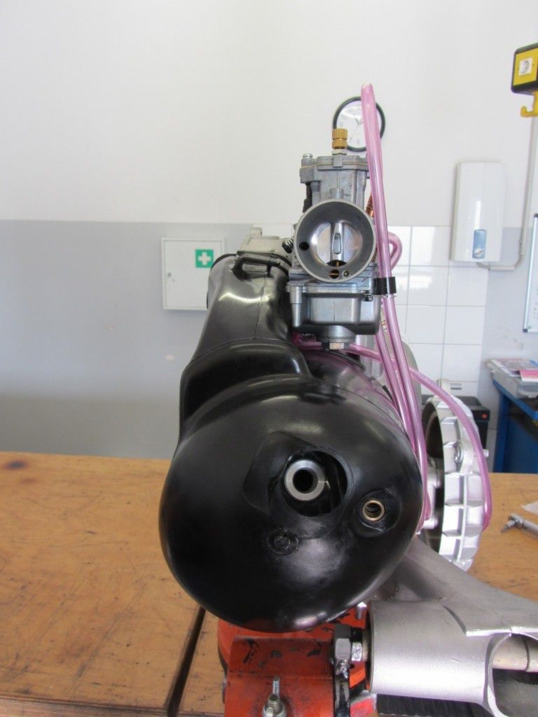
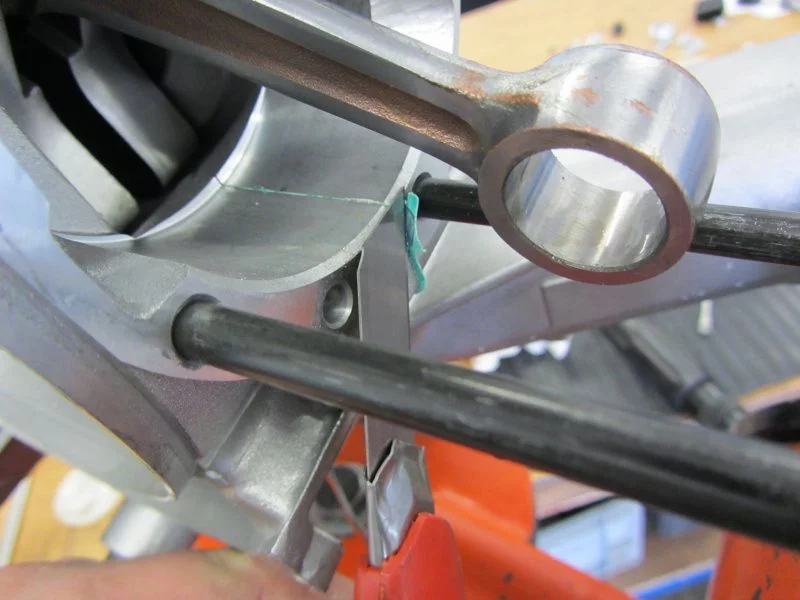
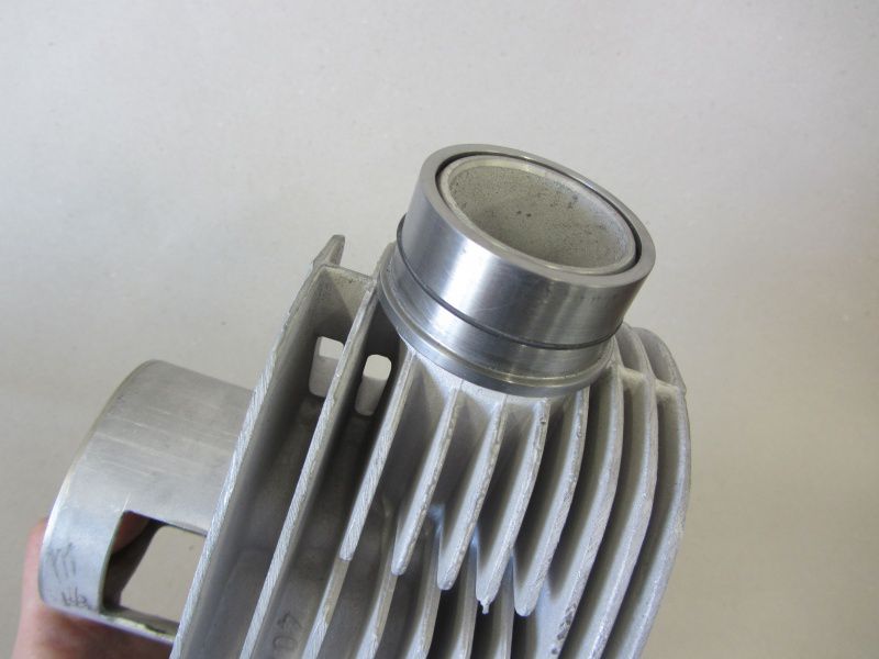
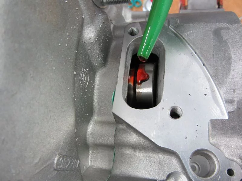
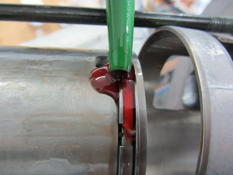
As already mentioned, the inflow of the 28 Keihins poses a potential problem area.

As a result, the inlet is slightly above the lowest position in the tank there is a risk that the gasoline flow will be obstructed by an air bubble.

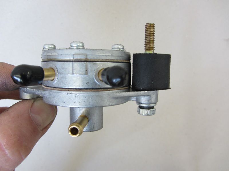
To avoid this problem as much as possible, we are installing one Fuel pump.

The petrol pumps that are usually used are operated via a vacuum membrane, so it is best to position the pump at the lowest point in the system.

The Silent rubber serves as a suspension and should, if possible, prevent the gasoline from foaming due to excessive vibrations.

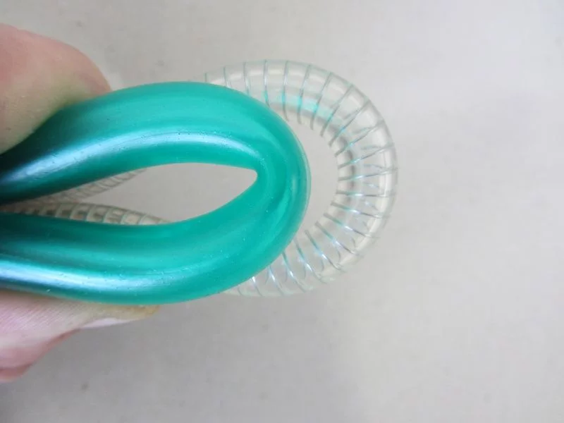
We use a very tried and tested fuel hose Toyox hose. A metal spiral inside, high wall thickness and a very small possible bending radius characterize this hose and make it relatively insusceptible to mechanical influences.

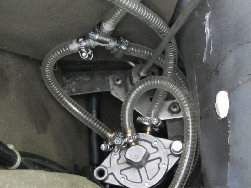
Provided with the hose salad that is necessary for the time being, it then looks like this.

For explanation:

The upper, middle connection of the pump leads to the vacuum connection in the membrane box.

The connection on the right of the pump leads to the tank.

From the left connection it goes a little on one Y-connector from there the right connection leads to the carburettor. The upper connection forms the return to the tank. The outlet for the return is positioned a little higher so that any air bubbles that may appear can make their way back up into the tank.

With a bypass system there is the possibility that the air is always pumped in a circle and the pump output is greatly reduced.

Diaphragm pumps and Keihin carburetors have something in common, a strong dislike for dirt.

The well-intentioned sieve on petcock in the tank keeps larger chunks out, but that is nowhere near enough. Smaller dirt particles tend to be deposited in the chambers of the pump until a heart attack occurs and the pump finally quits the service.

The fine Mr. Keihin reacts much more sensitively and immediately to dirt, constant overflow and booby behavior in the idle area are just two of the possible expressions of displeasure.

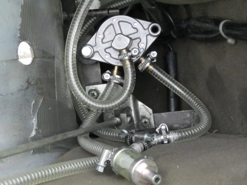
That is why we put a filter in front of the entire gasoline household.

The crystal clear OMG filter have also proven themselves in our racing team, here in the picture below.

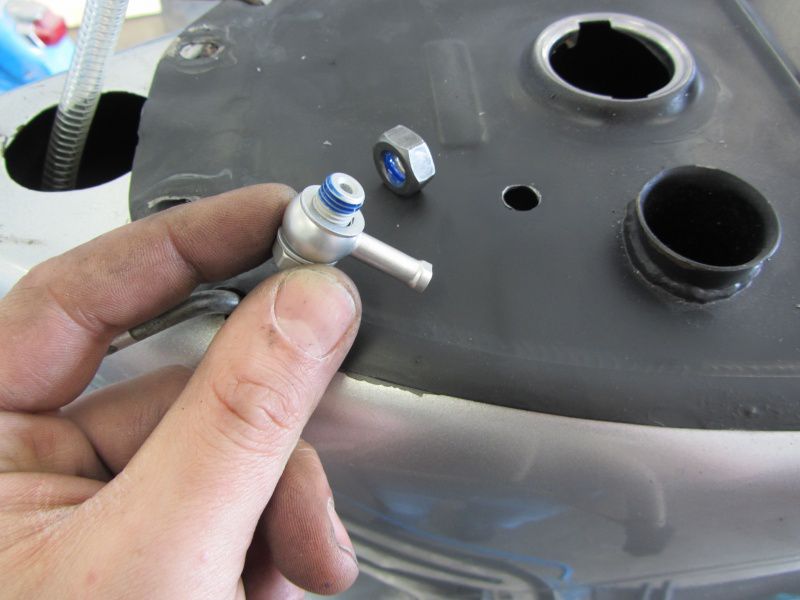
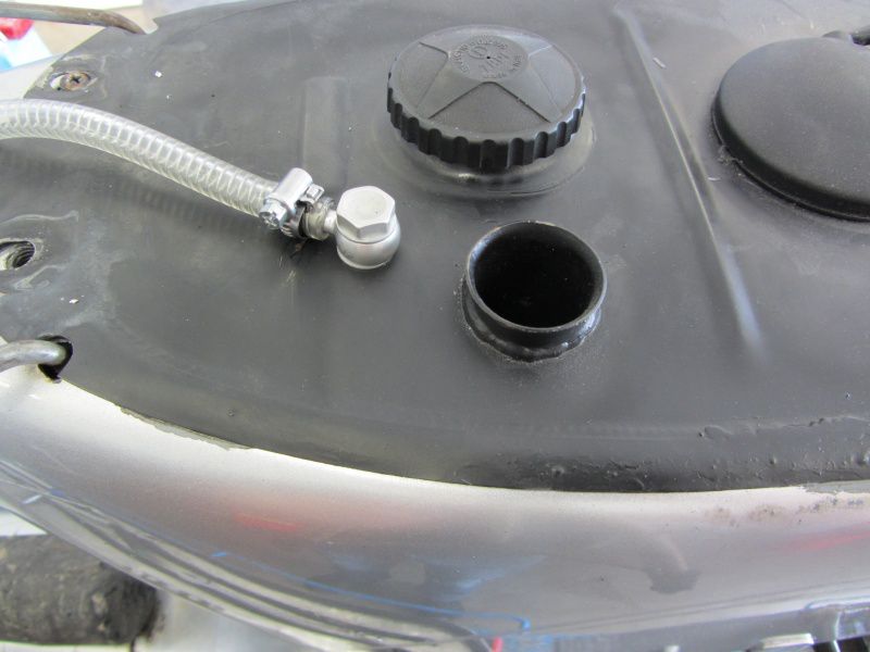
We use a for the return to the tank Brake banjo.

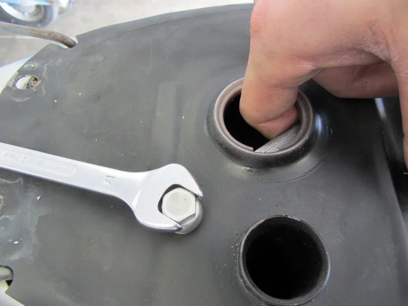
To do this, of course, a hole has to be drilled in the tank.

Please, please, drilling holes in a tank requires extreme caution.

So that the tank and humans do not end up as a ballistic experiment in low-earth orbit, the tank should be rinsed beforehand and, to be on the safe side, with water or CO2 to fill.

With threadlocking let's use the banjo.

A sure instinct is required when tightening the screws.

Return finished.

As with the braking system, the banjo comes with Aluminum seals attached.

With the front brake and a T5 fender, it continues tomorrow.

Today Jonas was our guest on our dynamometer.

With a Polini 133 in the gray cast iron version did the young man with our testFire magic After all, the exhaust already achieved a very impressive 28,3 hp.

In addition to the gray cast iron Polini, which Jonas worked on more than neatly, one can help Polini membrane , and a 35 Keihin PWK Carburetor the engine to its performance.

After a few small changes, we checked again today whether it managed to break the magical 30HP limit.

The first attempts with one French, Jonas own exhaust, looked very promising compared to the last P4 session.

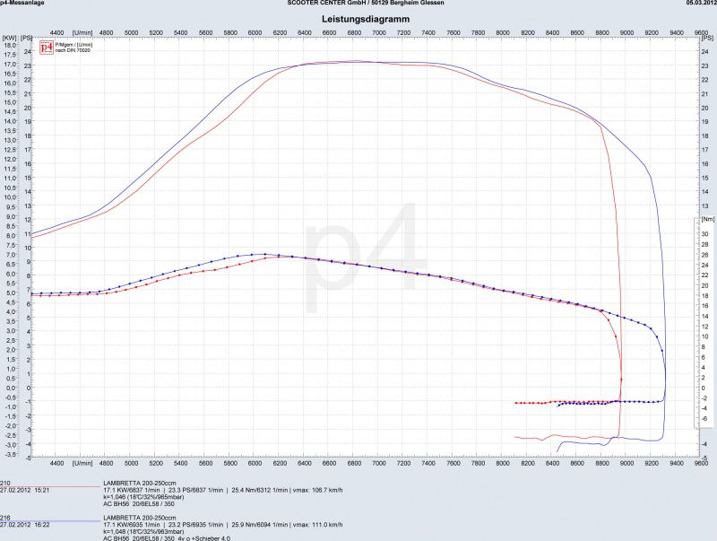
The change from the red to the blue curve is rather simple. The cylinder was mainly lifted with a 0,5mm thick spacer at the cylinder base.

It is nice to see from the two curves that the increased control angle and the resulting smaller discharge has a greater effect on the functioning of the exhaust than the reduced compression and the lower mixture acceleration due to the larger squeeze dimension.

Sometimes less is more.

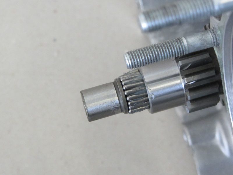
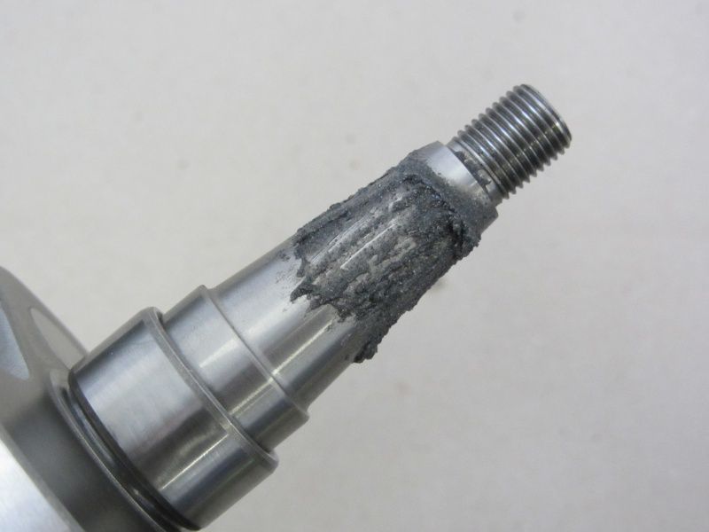
Unfortunately, the crankshaft gave up in the course of this series of tests, and the crankshaft stump on the pole wheel side sheared off.

28PS were probably a bit much for the simple racing wave in the long run.

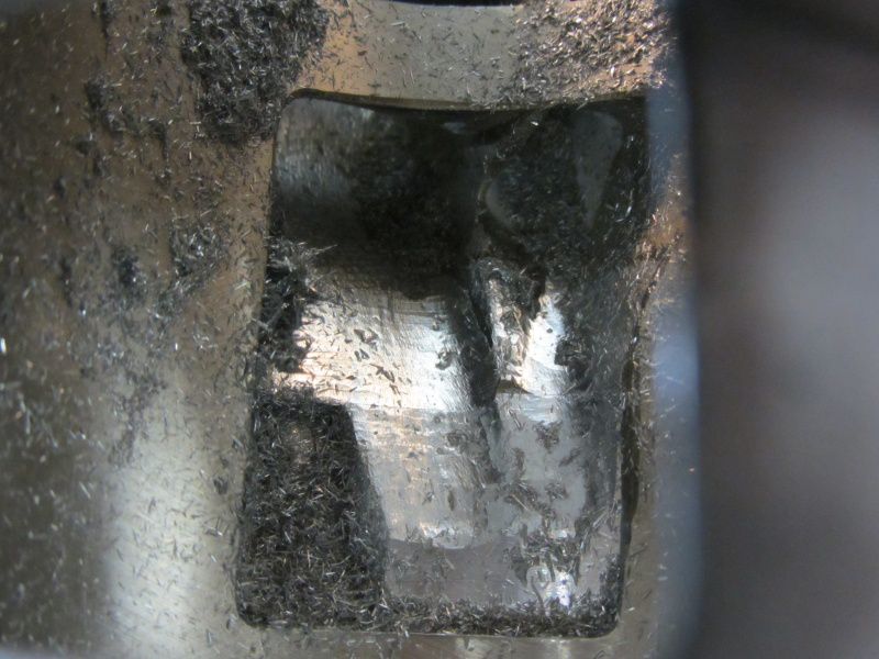
The aluminum chips in the boost port do not bode well ...

Hoping it will Motor housing didn't catch too much, we already have Jonas with a new one BGM crankshaft 51mm stroke and 105 connecting rod equipped - with this the new attack on the big 30 will be carried out in the near future.

From our side - Jonas succeeded a lot !!

If you are also interested in finding out which exhaust makes a bullet out of your engine or is better suited for the big tour, then we can offer you a small selection of exhaust systems for testing on the test bench.

Contact:

pruefstand@scooter-center.com

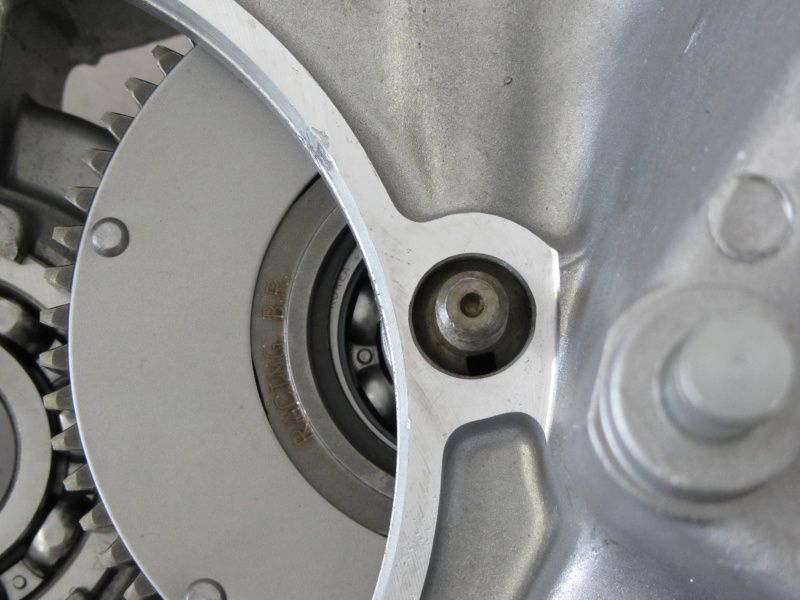
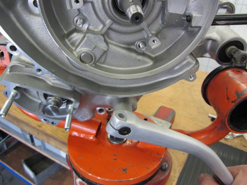
The next step is to install the clutch.

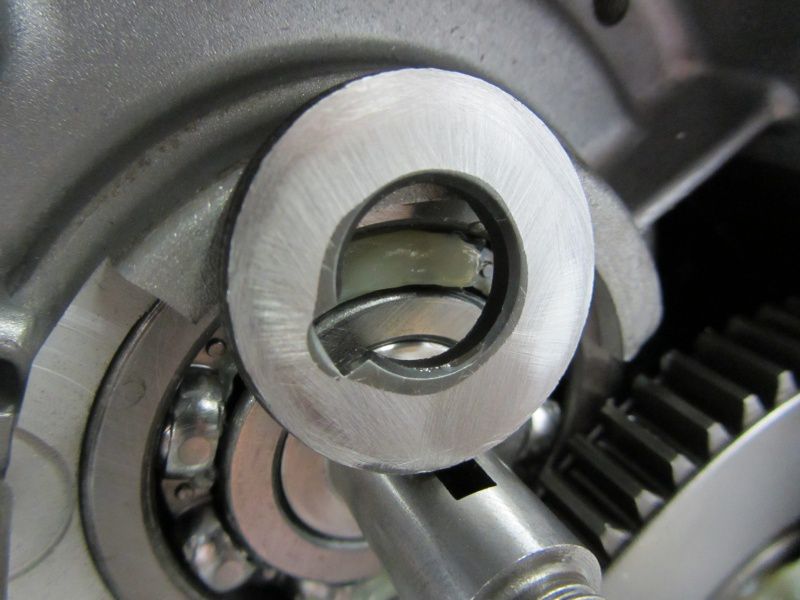
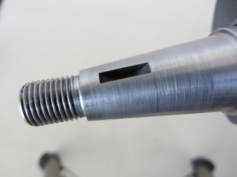
The spacer has a chamfer around the hole on one side. The side with the chamfer belongs in the direction of the crankshaft, as the crankshaft stub usually has a small radius at this point in order to counteract the notch effect.

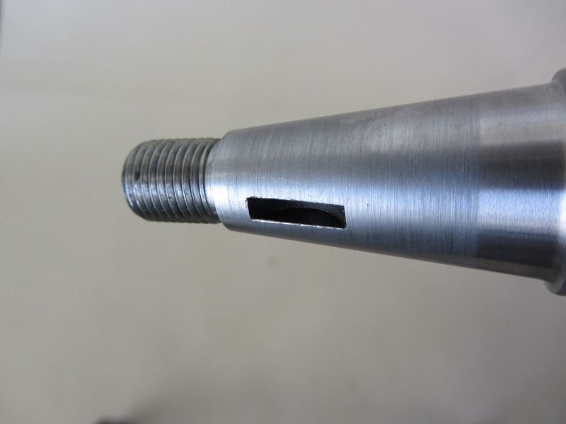
The crescent wedge or Woodruff key should be pressed as far as possible into the groove of the crankshaft so that it does not stand up when the clutch is pushed on and damage the clutch hub.

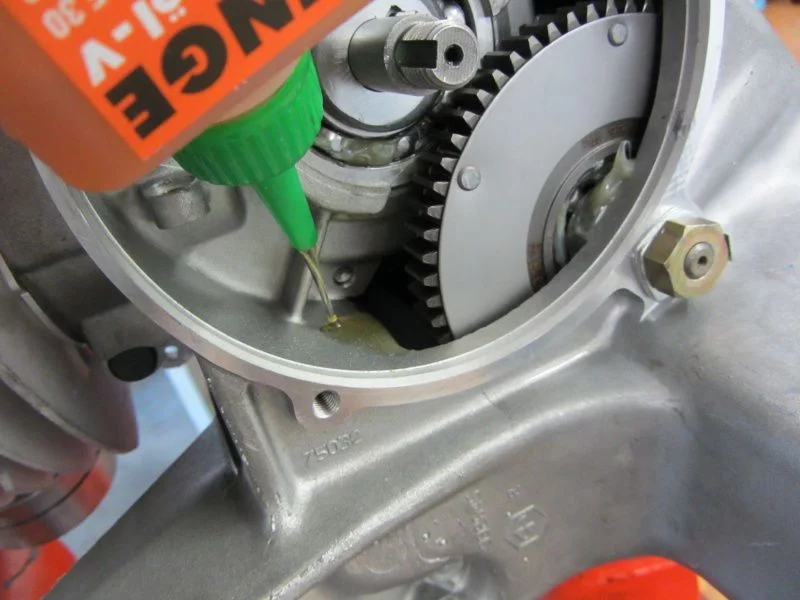
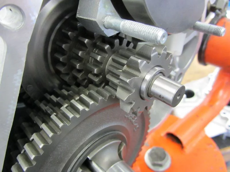
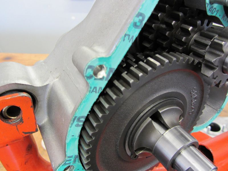
Before the clutch is installed, we still use the free access to the gearbox and fill in the gearbox oil.

As soon as the transmission oil is stowed in the engine, the clutch is mounted.

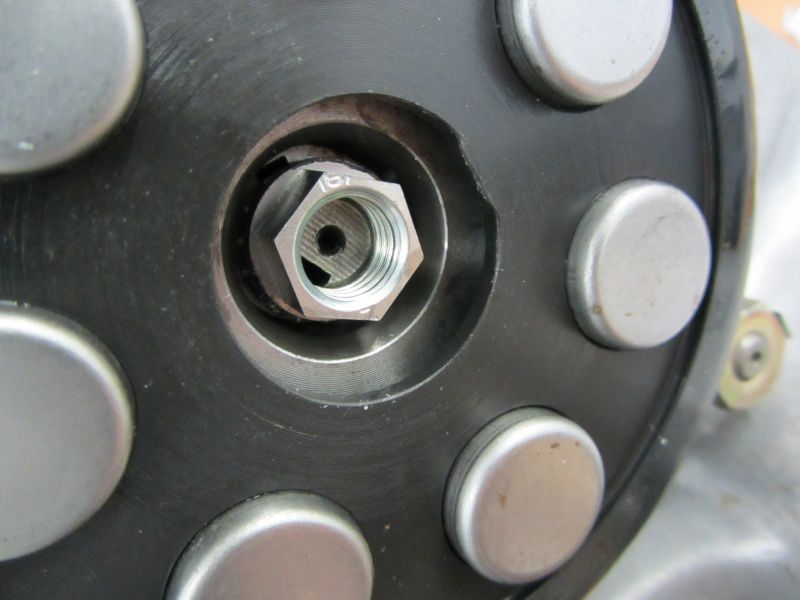
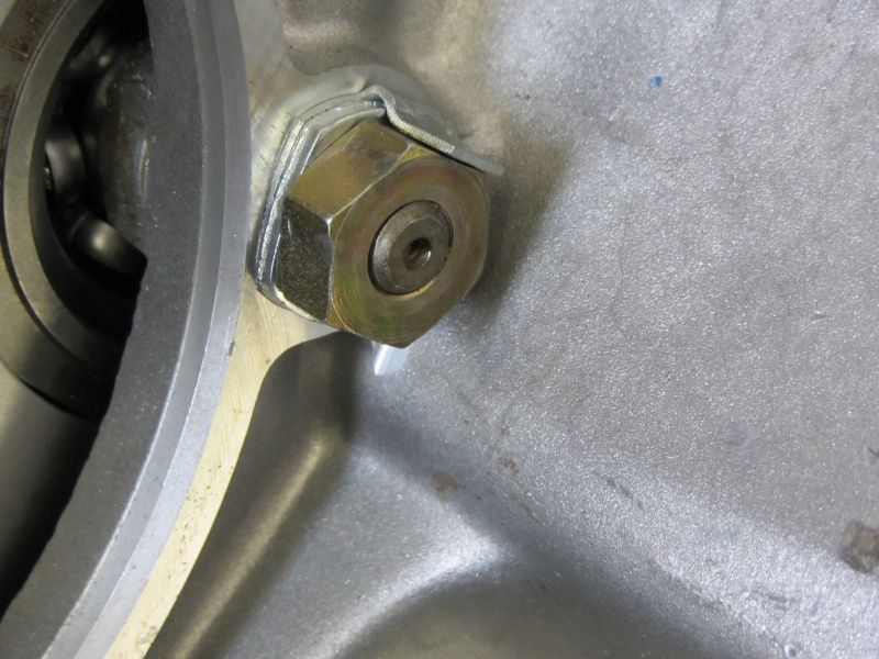
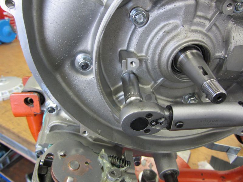
Fortunately, there are now other solutions than the well-known castle nut, which has certainly already driven one or the other Vespa screwdriver cursing insane.

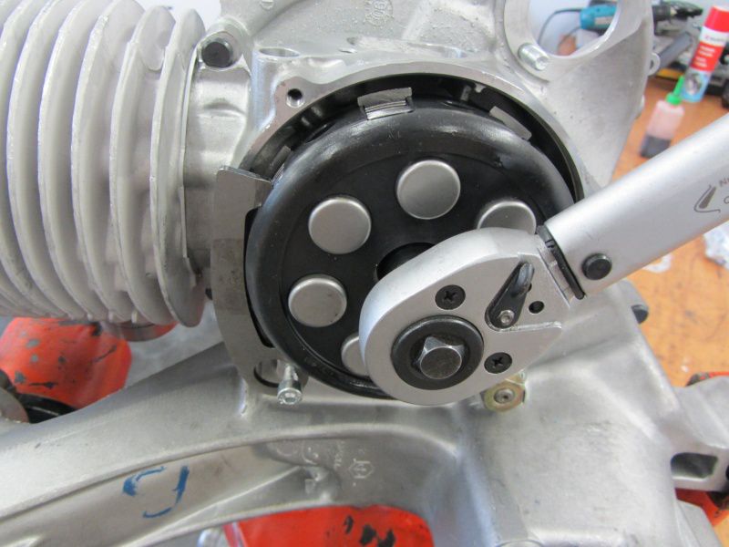
We have these nuts made in Germany. Unfortunately, elsewhere there are some Indian “qualities” on the market that cannot cope with the required tightening torque of 50Nm and stretch their arms.

Nut tight, now comes the thrust washer.

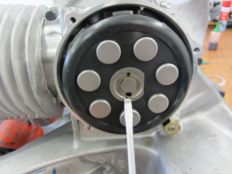
The retaining lug of the spring is guided through the larger of the two holes during assembly.

The pressure mushroom gets a touch of fat ...

and then it goes to the membrane box.

As tested, the float chamber of the Keihin is located below the lowest point in the tank. Unfortunately not the influx.

In order to avoid that a small air bubble at this elevated point will stop the fuel flow later during operation, we have to equip the Silver Fern with a fuel pump.

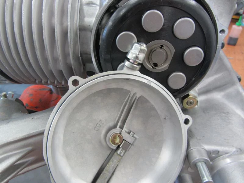
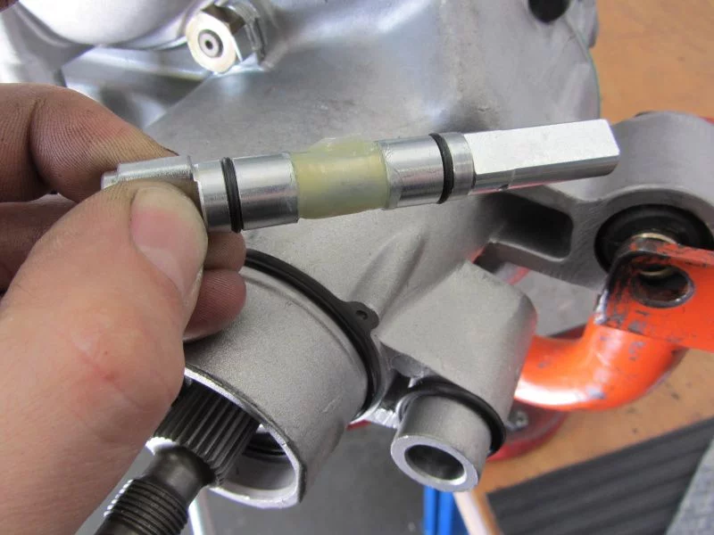
We put the vacuum connection in the membrane housing.

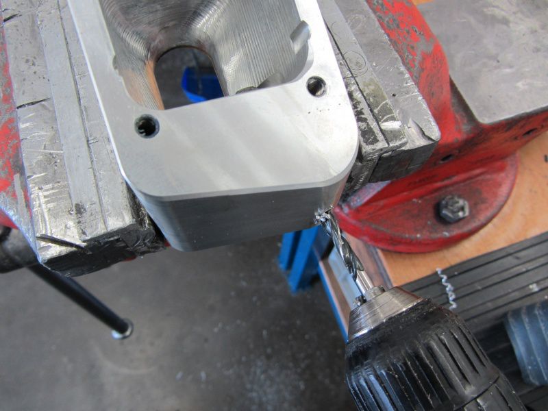
Drill…

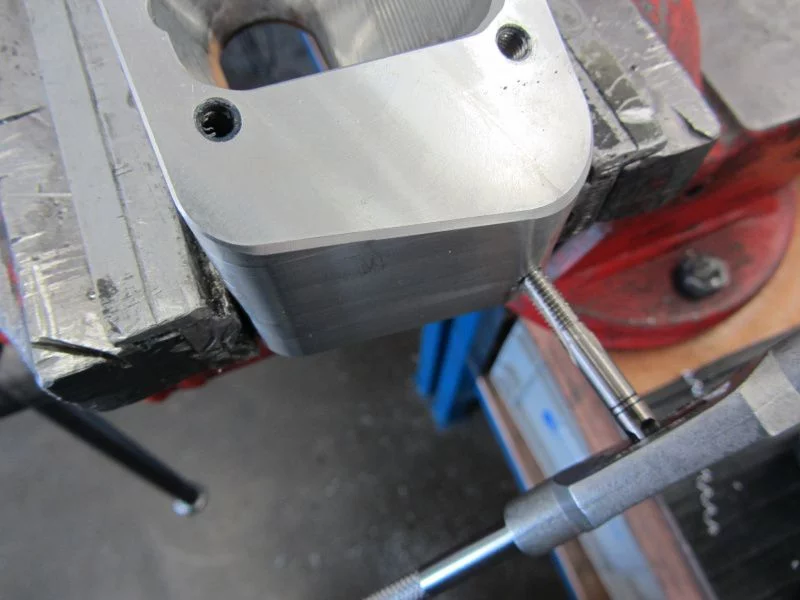
Insert the thread and ...

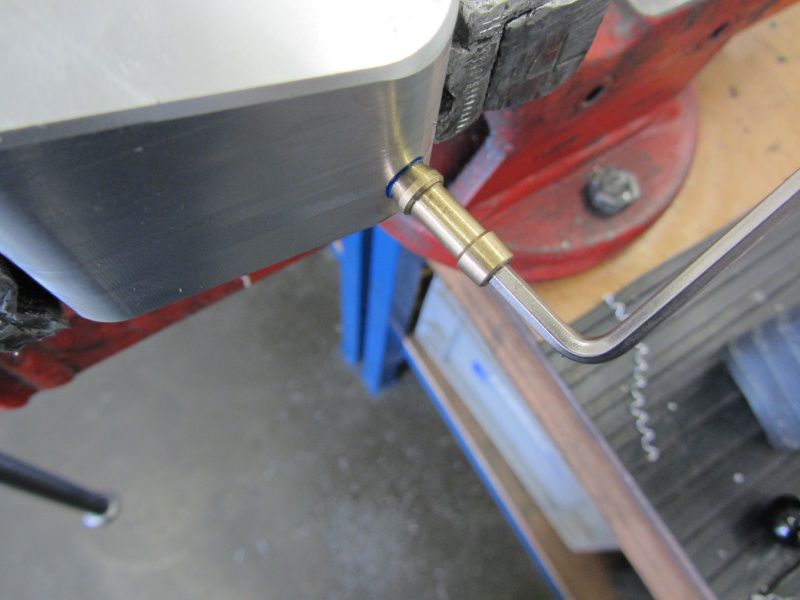
and use the countersink to create a small sealing surface for the cone of the vacuum connection.

The connection is screwed in with a little screw lock.

Then the suction device is installed with the membrane and seals.

As a test, we attach the carburetor in order to make any necessary changes with the engine still removed.

We shape the cooling hood a little with the heat gun so that the carburetor is straight.

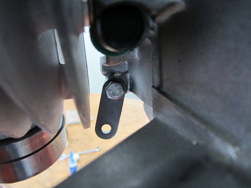
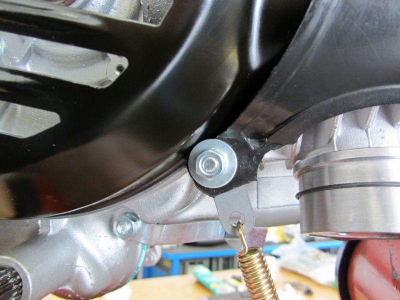
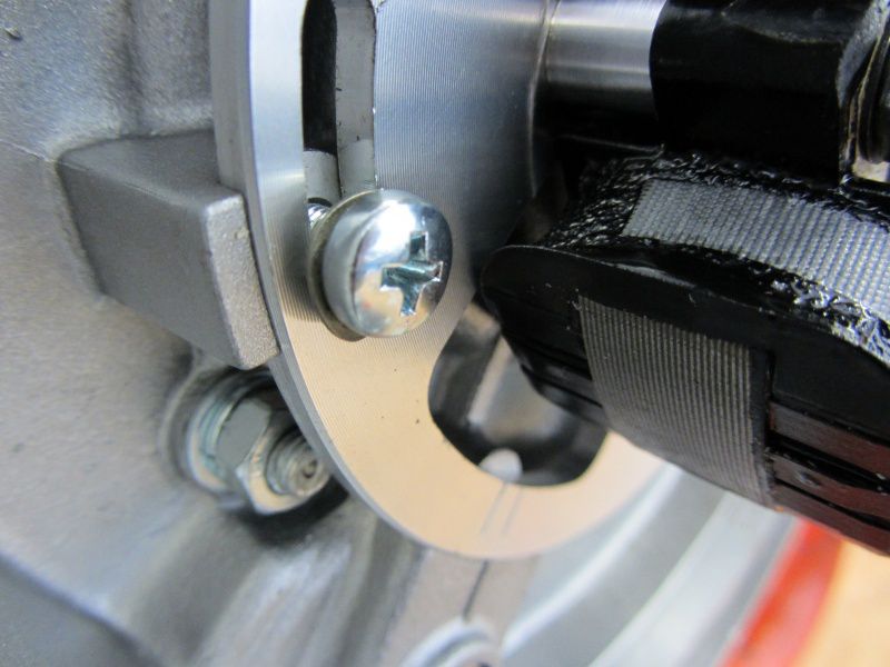
In the case of resonance systems, the manifold is often suspended with springs. For this purpose, a perforated plate is attached under the front screw of the fan wheel cover. If you just want to remove the fan wheel cover for checking or adjusting the ignition, you will usually be forced to unhook the spring every time. This sheet metal also works pretty well on the screw, since the surface is the soft plastic of the cooling hood and at some point the thread in the motor housing gives up.

Therefore we now fasten the retaining plate for the spring from the inside with a screw.

This, firmly glued in, then serves as a stud bolt on the fan wheel side.

Installation of the rear brake system.

The recess on the brake cam is provided with a reserve of grease and installed.

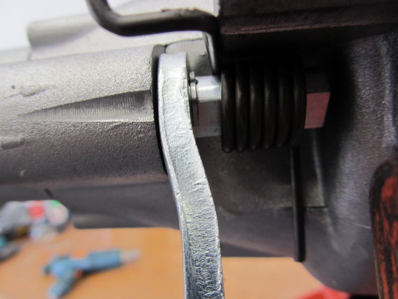
Brake arm, spring and finally the split pin.

After the dust cover has been installed, it is the turn of the brake pads.

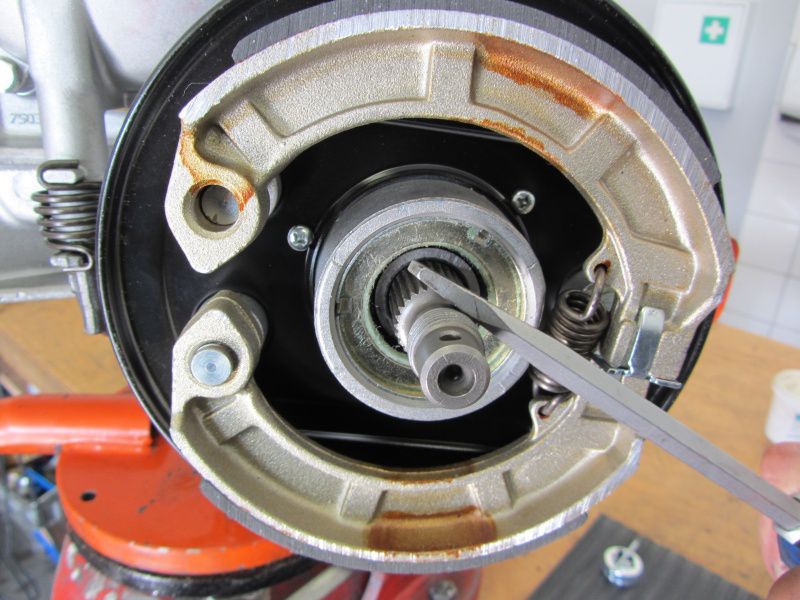
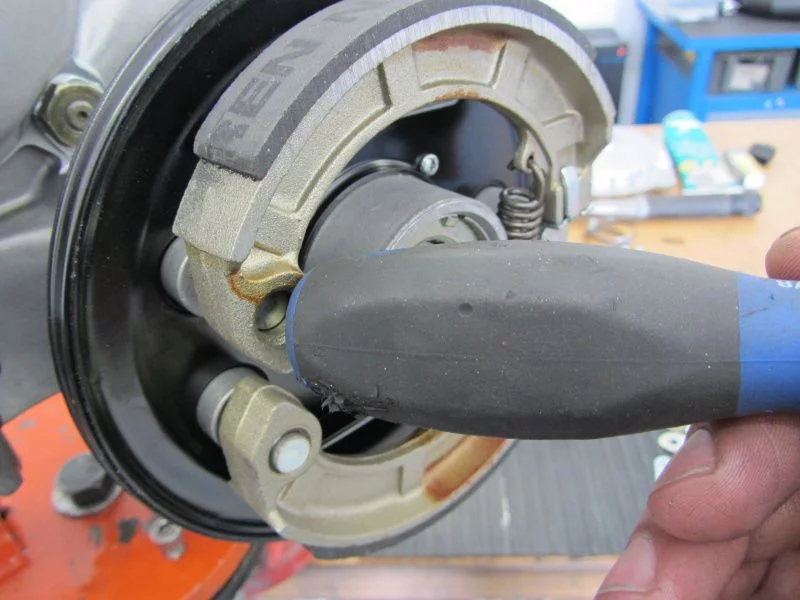
First insert at the bottom, then on top of the bolt ...

Then lift the top covering onto the cam with a screwdriver.

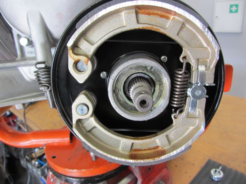
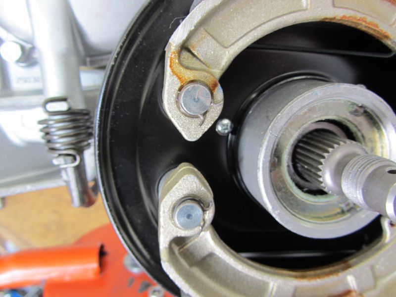
and then you can snap the covering into its actual position with a light bouncing blow. -Attention! Hands off!

Fuses are still on the bolts and you're done.
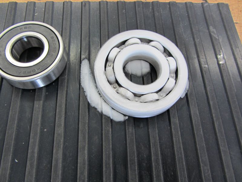
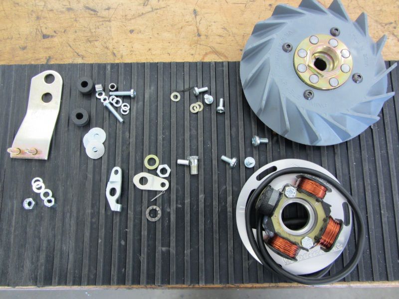
Here are the remaining parts that will be distributed on the engine.
The ignition system ..

is fastened with M5 screws and corrugated washers.

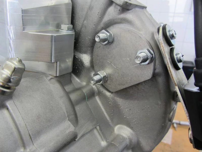
The retaining plate of the CDI is still mounted and because electric starters are only for .. well .., we don't need an electric start, so we close the hole with a cover plate.

Just quickly threw the fan wheel on it and then the wedding can begin.

Have a nice, sunny weekend!

Until Monday!

Alex

We clean the motor housing thoroughly before assembly brake cleaner and compressed air, because after all we have produced quite a bit of aluminum chips.

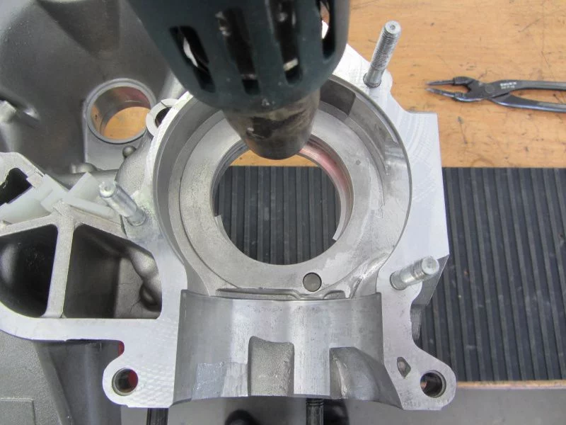
To install the bearings, we heat the motor housing with a hot air blower to approx. 90 °.

The ball bearings are with Cooler spray treated. Almost all of the bearings have been shrunk in this way.

The only exception is the B188 for the main shaft in the small, alternator half. We use that for the installation matching tool.

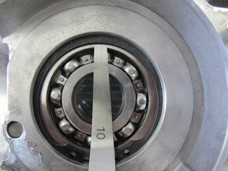
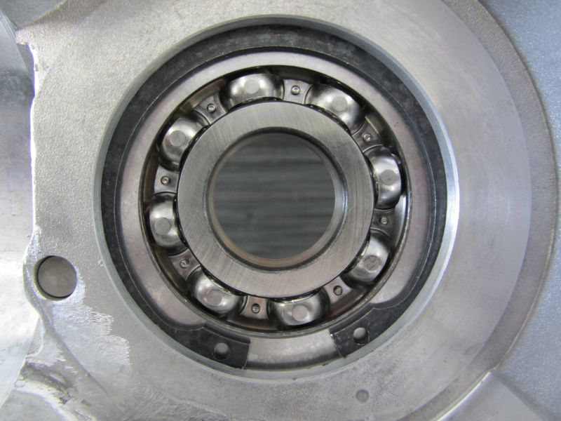
As soon as the bearing is on the coupling side, we use a feeler gauge to check the clearance to the circlip.

We also match the axial play Shims .

The whole action is intended to prevent the ball bearing from being able to move axially in the seat when the engine is warm and so sooner or later wear the bearing seat.

In the end, we come to 3 / 10mm with our motor housing, which has to be compensated.

We do the same with the 6204, the rear wheel bearing.

It continues with the shaft seals.

We use one to match the Lusso main shaft internal shaft seal.

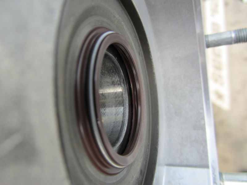
One with on the crankshaft Metal shaft seal.

It is important to check after installation whether the shaft seal is in contact with the bearing.

If that were the case, the shaft seal would be destroyed within a short time by the frictional heat generated.

For the next step you should be a calm character.

The auxiliary shaft is inserted with the axis into the motor housing so that the bearing surface still protrudes.

With a little fat they will be 21 loose needles glued to the auxiliary shaft axis.

As soon as all the needles have been sorted, the axis can be pushed into the housing as far as it will go.

The auxiliary shaft axis has a recess for the nose on the locking plate.

Together with the washer, the axle is then tightened to 35Nm and secured.

To install the main shaft, we grease the chamfer for the shaft sealing ring so that the sealing lip does not turn over when it is pulled in.

brake drum let's pull the main shaft into the bearing.

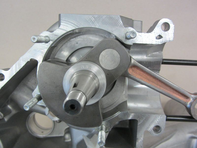
The crankshaft still needs the bearing ring pitched .

The orientation of the bearing ring on the shaft is ensured with a spacer gauge.

On the one hand, so that at some point later we can replace the bearing ring with the puller and, on the other hand, so that the bearing ring sits far enough in the bearing.

Where we have the great piece in hand, we can make further preparations.

The Silver Fern is supposed to be used by a Vespatronic be ignited.

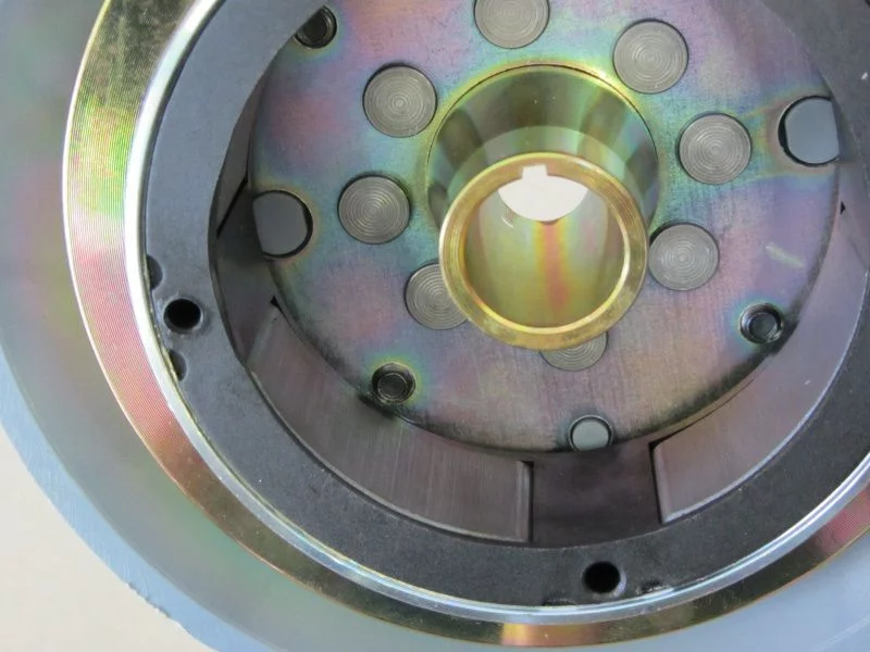
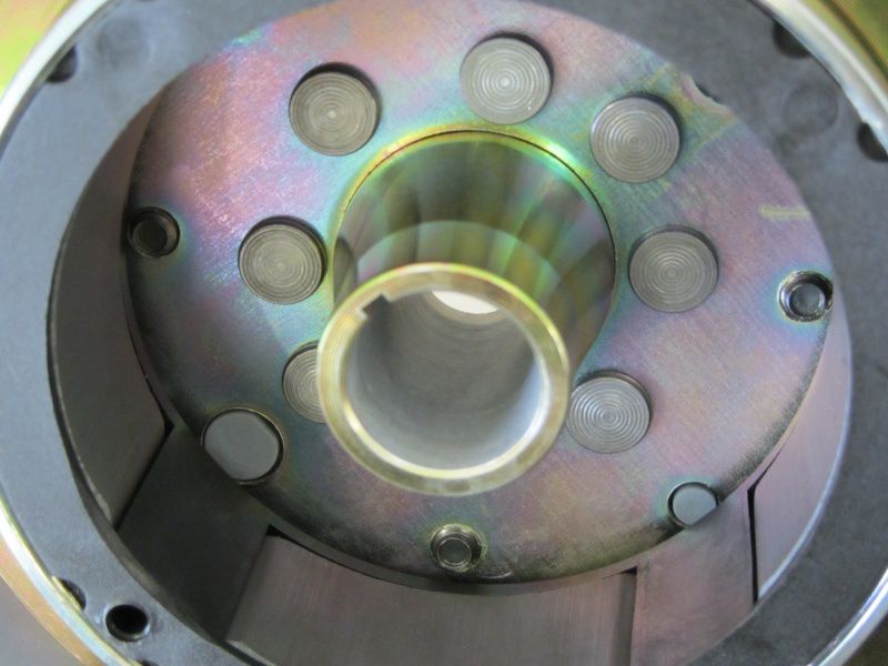
To be on the safe side, we grind the pole wheel of the Vespatronic Valve grinding paste so that any angle errors in the cone do not cause damage.

As soon as a uniform contact pattern emerges on the surfaces in the pole wheel and the crankshaft,

the cone should “glue” when put together.

Sometimes it is totally annoying to use the crescent wedge in the installed state with new crankshafts, because it does not seem to fit. This is often due to a burr on the keyway that spoils the installation.

Therefore we deburr the keyway on the Lima side.

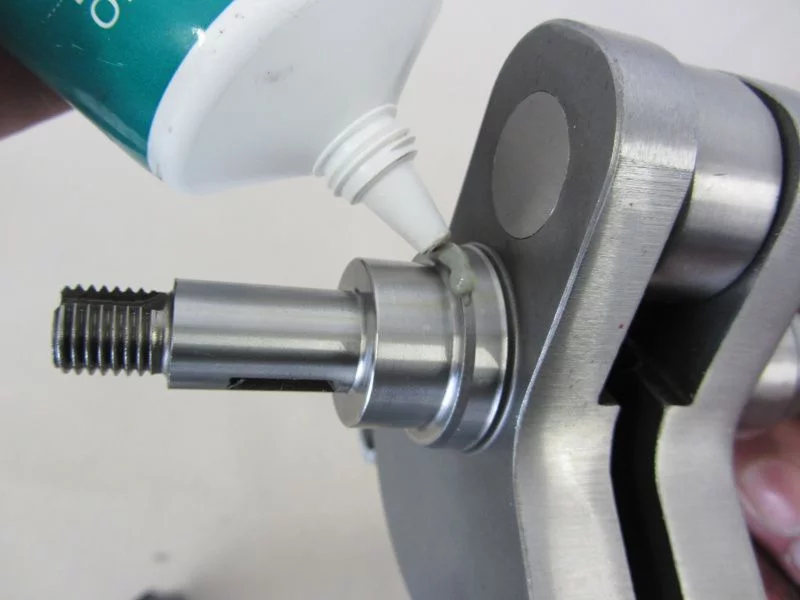
Before inserting the crankshaft, the chamfer for the shaft sealing ring is also provided with grease here, as on the main shaft.

We put the half of the housing, now complete with the crankshaft, into one Motor mount.

This is much easier to screw afterwards.

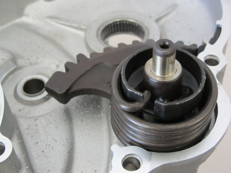
The second half of the housing is provided with an O-ring for the kick starter shaft, the same and the associated spring.

Uh! don't forget - that Kickerl! The pinion should be placed on the auxiliary shaft with a little gear oil.

We glue the pressure spring for the pinion with grease in the small half of the housing.

All open ball bearings also get a little lubrication so that there is no insufficient lubrication during the first few revolutions until the oil has spread.

The Housing seal is fixed with grease so that it does not slip when the halves are pressed together.

When pressing the housing halves together, it is necessary to use the Kickstarter to be pressed briefly so that the pinion can jump behind the kick starter segment.

As soon as the housing halves are in contact with tension, we put the Housing bolt .

The bolts are tightened step by step up to 12Nm.

Cut off the overhang of the seal.

and then you can continue with the assembly of the piston and cylinder.

The cylinder and the outlet port of the Newline are quite “close” friends, so it is advisable to try the port on beforehand.

In the assembled state it would be a bit of a nightmare to machine the nozzle ...

Upper and lower connecting rod bearings get something Motul with me for the first few meters.

Just like the piston pin, rings and the cylinder liner.

We grease the O-ring in the cylinder head into the groove so that it does not slip and get damaged during assembly.

Tightened crosswise step by step down to 20Nm, everything should also be tight here.

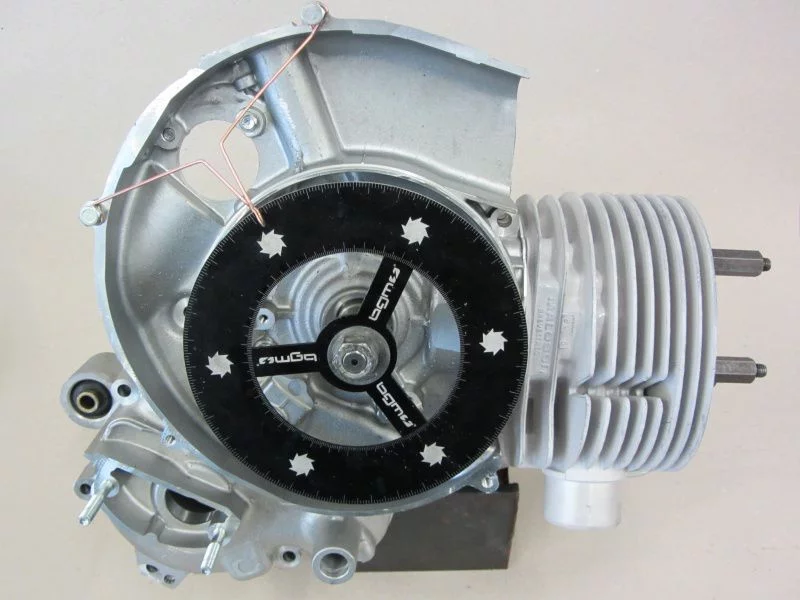
With bearing dummies, we insert the crankshaft into the engine housing to measure the control angle.

We will soon have the storage dummies available for you in the shop.

The two housing halves are fixed with the 4 nuts in the stator housing and the cylinder is for measuring the control angle assembled.

The Newline likes rather low steering angles. At the outlet below 190 ° with a discharge of 28 °.

With a 1,5mm thick Spacer for the cylinder base and a Malossi base gasket, we come up with it
129 ° overcurrent and 185 ° exhaust.

If the squeeze size is still within limits, then we have a very good basis on which we don't really have to change anything.

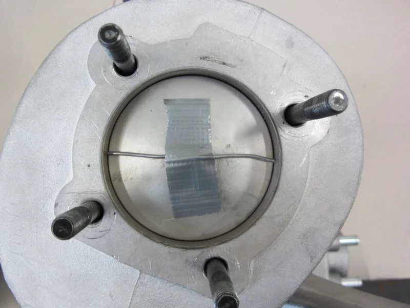
In order to take the squeeze dimension, i.e. the distance between the piston and cylinder head at TDC, we attach a piece of solder to the piston crown with adhesive tape. The crush dimension should always be determined parallel to the piston pin, otherwise the piston will tilt due to the running clearance in the cylinder and thus falsify the dimension.

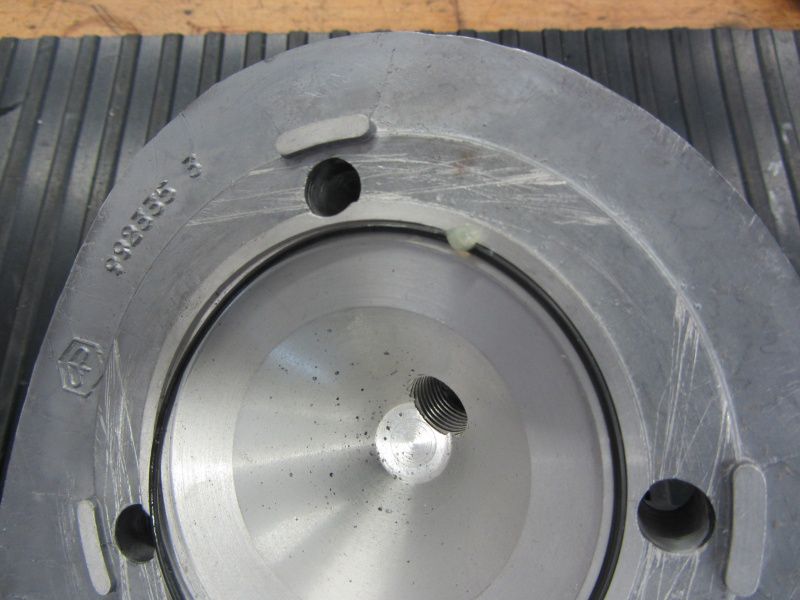
For the cylinder head, our choice is that of S&S machined Piaggio cylinder head with an adapted combustion chamber for our purposes.

The Malossi is in one too Version with cylinder head available. However, the cylinder head supplied is intended for a 57mm stroke and is therefore unsuitable for our purposes, as the compression ratio increases with the increase in displacement. This and the rather high proportion of squishy areas in the Malossi cylinder head lead to a higher thermal load.

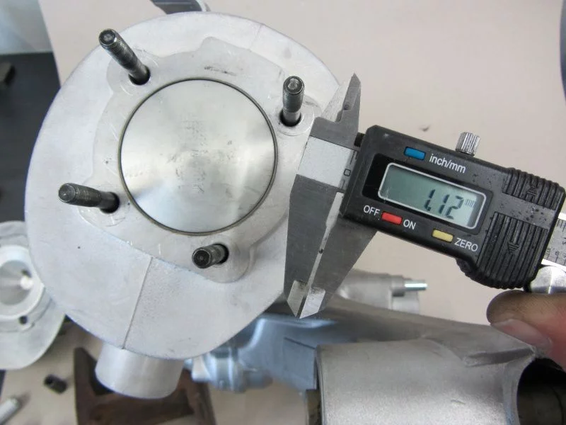
Mmmh… 1,1mm are a bit tight.

In order to get a higher squeeze dimension, we add an additional cylinder base gasket and thus come to 1,3mm at control angles of 130 ° to 186 °.

Next, the overcurrent channels are adapted to the motor housing together with the 1,5mm spacer.
First it is scrubbed again

and then smoothed.

With the Malossi and Polini 210 it is not only necessary to adapt the motor housing, but also the cylinder in the area of ​​the overflow ducts.

Since the Malossi piston allows the mixture to reach the overflow channels very easily thanks to its open design (Malossi CVF), it is not necessary to mill huge pockets in the lower area of ​​the overflow channels.

The cylinder will be completely milled and tomorrow it will be the innards, i.e. the gearbox, primary drive and the clutch.

Today we are preparing the Malossi 210 for installation.

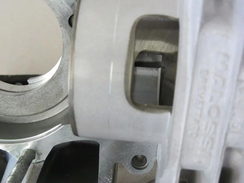
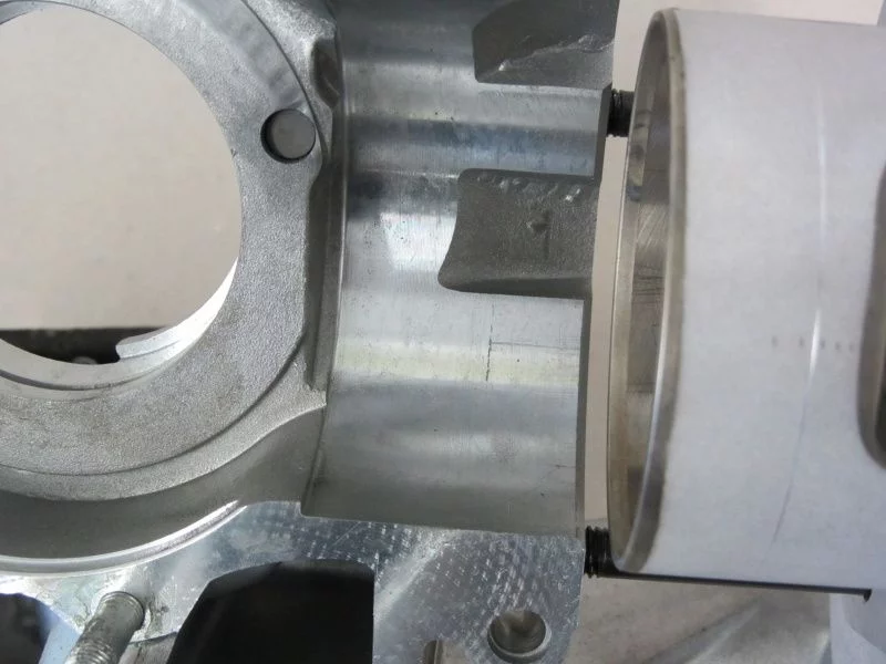
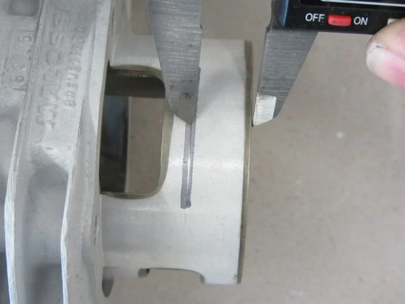
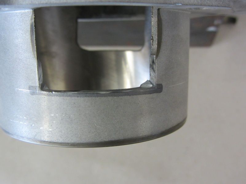
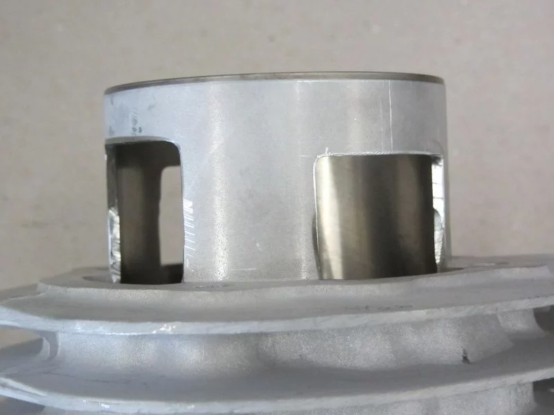
So that the full depth of the original overcurrent ducts in the motor housing can be used, the windows in the cylinder base are expanded.

Remove the depth of the channels and transfer it to the cylinder base.

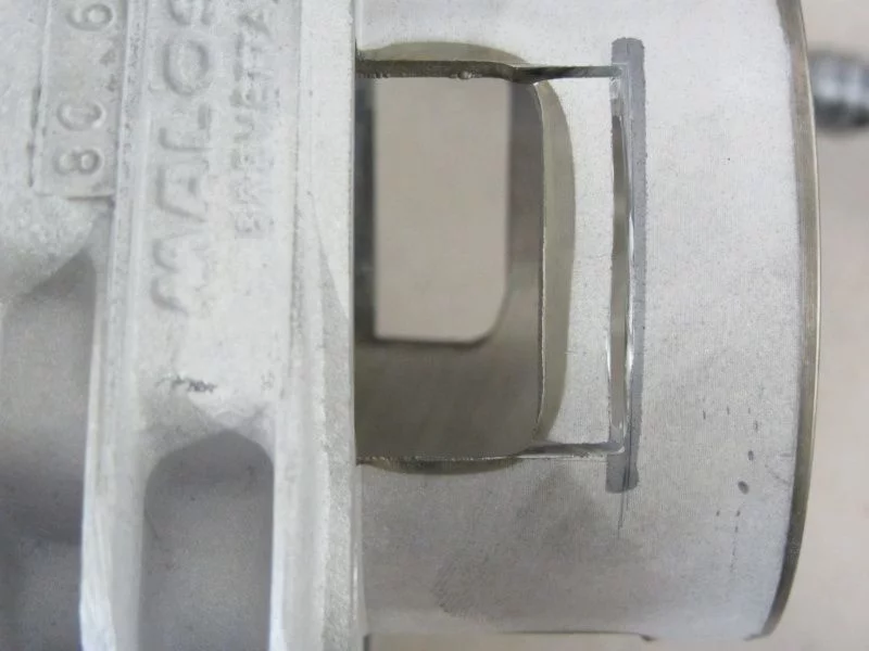
The window is first roughly cut out with a cutting disc.

It is important not to go to the final size, there should not be any sharp edges and corners. In the cylinder base in particular, it is important that the windows have a radius, otherwise cracks can quickly form out of the corners.

The coating in the corners of the raceway is now removed so that the coating in the raceway is not damaged in the next step.

For those of you who are tenderly strung please do not look at the next picture.

Here the cutout is removed with a slight * tick * of the hammer.

The resulting window is then made pretty.

The whole thing all around.

Tomorrow we will tackle the ducts as such together with the motor housing.

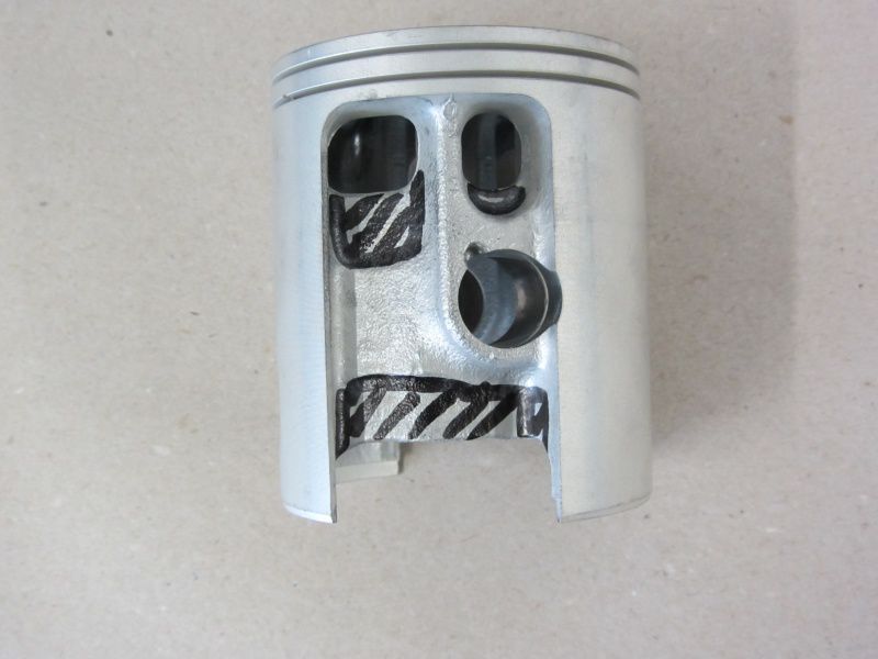
That leaves the piston.

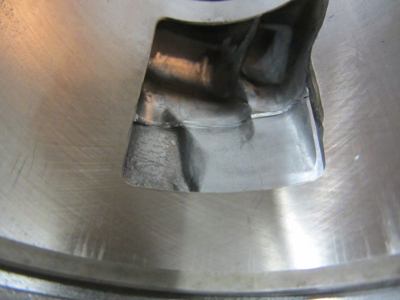
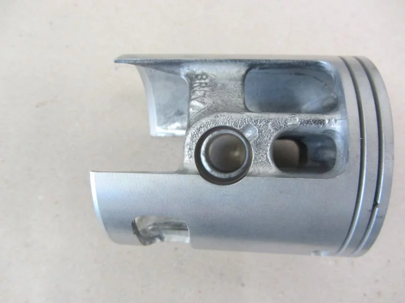
All black marked areas are removed and then smoothed.

now about 20gr. the piston looks lighter like this.

We don't want to withhold that from you! The first test run of the 130 Polini EVO engine. The motor is still in the motor holder and equipped with jet nozzles!
Many thanks to Thomas the Second, who edited the video for us in his spare time. Thomas will soon be joining us at the Scooter Center begin. We are looking forward to it!

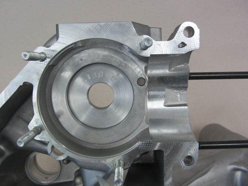
The new heart of the Silver Fern comes from a PX200 motor housing on which we put an MMW Evo2 membrane box.

The lower part is mounted first for marking.

The inlet is roughly milled using these markings.

After we have removed what feels like 2kg of aluminum from the inlet area, the rough shape looks like this.

Then the transitions to the membrane housing are adjusted and finally the surfaces are made stylish, because the eye also moves with the internal motor ...

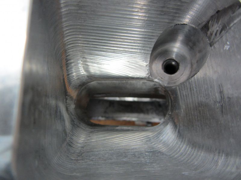
Unfortunately there is a small area at the bottom right of the picture with a few cavities, i.e. gas inclusions and impurities in the casting. Visually not exactly a flaw, but technically completely safe.

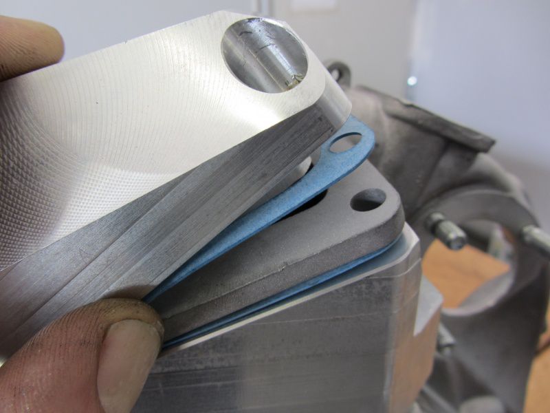
The discreet inlet can no longer be sealed with a conventional seal, so cut something suitable out of sealing paper.

Straight edges can be easily cut with a cutter and steel ruler.

The easiest way to punch out the holes for the fastening screws is with a handle punch when you are at hand.

It continues on Monday ...

The “Silver Fern” comes from the close circle of friends of the SCK and will be used again this year after a long break for everyday life and trips to Vespa meetings.

We would like to introduce you to the associated engine concept here.

We are aiming for a performance of around 25HP with a lot of pressure in all positions.
With enough torque, the transmission can be translated for a long time in order to achieve a good cruising speed at relatively low speeds.

First of all, roughly the ingredients for the engine.

That comes as a cylinder Malossi 210 for use. Since we are aiming for torque and therefore want to install a crankshaft with a 60mm stroke, it falls Polini 210 still out. The new Version for 60mm stroke is not yet available at Polini.

For the crankshaft, we fall back on the tried and tested, the so-called Bell waves have established themselves in performance-oriented motors with diaphragm control.

There is also a lot of choice when it comes to the intake manifold, we decide on one Evo2 from MMW in the one BGM membrane with GRP panels tinkering.
Before that we then a 28 PWK from Keihin strapped.

A DRT “Spitfire” countershaft can be used to distribute the horses to the 4 speed levels.
With that and a short one 4th gear of the T5, useful gear steps can be realized. Overall, the translation would be quite short when using an original PX200 primary. That's why we're implanting one in the new heart of the Silver Fern Malossi primary with a translation of 24 / 63z.

The Scooter and Service Newline ensures the right vibrations in the exhaust department.

For you, we record every work step in as much detail as possible.

Tomorrow we will start adjusting the motor and diaphragm housing.

Last week Harald was a guest on our Amerschläger P4 to check the carburetor set-up of his 225 Monza and to optimize it if necessary.

Here are the key data of the engine:

Cylinder: Monza 70mm bore

Crankshaft: BGM 60 / 110mm

Carburetor: Mikuni TMX 30

Exhaust: JL-KRP3

Steering angle: 186 ° / 126 °

Crush dimension: 1,7mm

The diagram shows the change from the red to the blue curve.

By using a thicker slider and changing the needle position, more pre-resol power and more overrev could be realized.

Sven Kauke presented his current project to us on Saturday.

A very successful concept in our opinion!

The inner values ​​were then checked on the test bench. To explain, we would like to add that the cylinder itself has not undergone any revision, so it was plugged onto the engine as it is delivered by Parmakit.

In this case, the measured control angles are 128 ° / 190 °. With a little more outlet angle, the Bertha would surely conjure up a completely different curve - maybe Sven would like to work the cylinder again with his fingers.

Here are the key data:

Cylinder: Parmakit SP09

Crankshaft: BGM 51/105

Carburetor: Keihin PWK 33

Suction system: Polini membranes on 2 flaps with Straw speed connector

Ignition: Vespatronic

Exhaust: Big bertha

Race team colleague Dennis chased his long-distance engine over the P4 with us on Friday.

Here are the key data of the engine:

Cylinder: Parmakit 144ccm, 60mm bore

Crankshaft: BGM 51/105

Carburetor: Keihin PWM 38

Exhaust: Big bertha

With an initial nozzle, auxiliary nozzle 52, main nozzle 160, needle DEG, a very useful result was achieved with the “first firing”. With the built-in 2: 46 primary from DRT is that certain
very nice engine for long distances like the Nürburgring or the Bilster Berg.

Vespa exhaust test

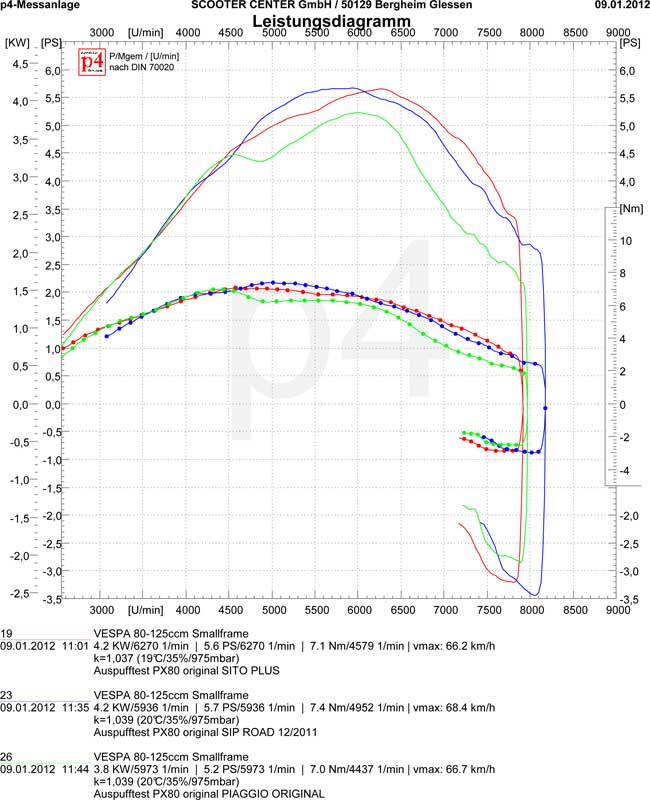
As part of our development of the 125cc cylinder for the PX80, different exhaust systems were tested on a completely original PX80 in order to have references available for comparison.
We tested the following exhaust systems:

Original Piaggio (green curve)
SITO Plus (red curve)
SIP Road (blue curve)

It is remarkable how brave the Sito Plus does against the strong Road. Up to 4500rpm, the original pot is not only at eye level but even a little bit stronger to then say goodbye to the other two in a spectacular way.
As expected, surprises cannot be expected from an exhaust change on such a tame cylinder. The absolute numbers only result in a difference of a maximum of half a horsepower.

However, it is more important to consider the performance curve here. So the engine with the Sito Plus at 7000rpm still has a remarkable 5HP on the rear wheel, the original pot only has 3,5HP.
The 7000 rpm correspond to approx. 80 km / h in fourth gear (the diagram shows measurements in third gear). So there are only 2,5 HP more on the rear wheel by changing the exhaust with the Sito Plus.
The result is that the motor can maintain this speed much better without being forced to its knees by increased driving resistance such as an incline or headwind.
The SIP Road, on the other hand, has more torque in absolute terms, but this is applied much earlier and, in direct comparison to the Sito Plus, is only noticeable in the draft or mid-speed.
Here, the final translation might have to be lengthened somewhat in order to utilize the full potential of the system.

This week there is the final report on our conversion cylinder for the PX80. With this complete kit, each PX80 can easily be brought up to 125 cc displacement and benefit from the significantly lower insurance rates associated with it. All you have to do is change the cylinder including the piston and head, the short motor remains unopened!

Originally the 80ccm engine has about 5HP on the rear wheel.
The SCK conversion cylinder increases the performance by a whopping 60% to a remarkable 8PS, all with extreme reliability.

We are already above the level of a DR135, despite 10cc less displacement!
The diagram shows the direct comparison between the DR135 (red curve) and the new 125cc conversion cylinder.
In conjunction with a longer gear ratio (possible by simply replacing the clutch pinion), the top speed is also greatly improved.

Another big plus point is the significantly cheaper insurance due to 125 cc displacement instead of 80 cc.
In addition, with a vehicle that has been converted to 125cm, you are not only more confident and cheaper on the road, the consumption is also usually cheaper because the significantly higher torque means that you no longer have to constantly drive at full throttle in order not to represent a traffic obstacle.
Something that may only become apparent at second glance is the significantly improved resale value of the vehicle. Holders of a car driver's license, if it was issued before April 01.04.1980st, 125, are able to drive motorized two-wheelers up to XNUMXccm without having to pass an extra test.
As a result, the market value of the 80cc vehicles specially designed for the German market was reduced substantially overnight. Anyone who has the appropriate driving license will use a more powerful 125cc vehicle than a weaker 80cc drive.
The conversion will make the vehicle much more attractive for a possible sale.
All in all, the cylinder purchase pays for itself quite quickly.

Two vehicles equipped with the conversion cylinder were on the road for several thousand kilometers without problems or breakdowns in 2011. The drivers are very satisfied with the performance and the low consumption.
We will test a few more optimizations during the week, especially with regard to performance, and then give our GO.

Here is a direct comparison between an original PX80 with SITO Plus sports exhaust (blue curve) and our 125cc conversion cylinder with original exhaust (red curve):

[Nggallery id = 6]

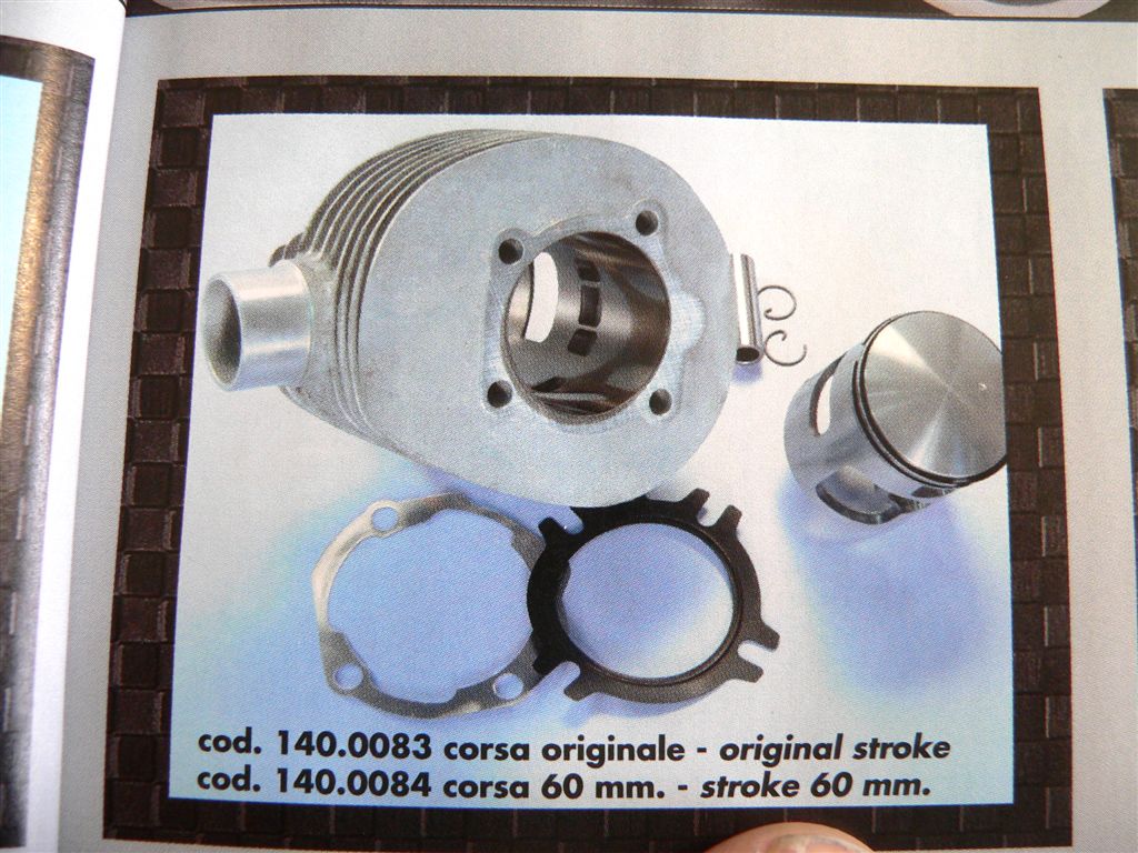
As already announced, Polini brings the 210cc cylinder in a version for use with a crankshaft with 60mm stroke (standard 57mm). The already available cylinder for 57mm stroke can only be driven to a limited extent with a crankshaft with 60mm stroke because the piston has an upper so-called L-ring.
This type of ring includes or forms the upper piston closure, so it controls the channels and not the piston upper edge as usual. If you now use a crankshaft with a 60mm stroke, the 3mm extra stroke must of course go somewhere ...

Since the piston moves 1,5mm more up and 1,5mm more down, the cylinder must theoretically be lengthened by this 1,5mm. For practical reasons, for the sake of simplicity, a suitably strong base or head gasket is simply used.
The problem with the two-stroke engine is that it also has an enormous influence on the exhaust and overcurrent control angles, which are important for the performance characteristics. To make matters worse, in the stupidest case you do not change both to the same extent, but usually take advantage of the overcurrent angle. Both values ​​(outlet and overflow angle) should always be in a ratio for the best possible power output.

In the case of the Polini, it looks like you are forced to use a foot seal. If you were to use a head gasket, the L-ring placed very high on the edge of the piston would simply rebound out of the raceway.
If a foot seal is used, the control angle is generally raised and, as already mentioned, the values ​​are taken advantage of in favor of the overcurrent angle.

This can lead to the engine starting too late with its power output and also being stalled in the upper speed range by a pre-exhaust angle that is too small (the angle that the piston releases the exhaust in front of the overflow ducts). This means that it can turn down further, but the power curve drops very quickly after the power peak.

In order to preserve the characteristics of the Polini, it would be better to recommend the use of a head gasket to compensate for the multiple stroke. As mentioned above, this is not possible with the standard Polini piston, otherwise the piston ring would rebound.

Facts ...

If the Polini 210 comes with 57mm crankshaft used, it has a very touring-friendly 123 ° overflow angle and 171 ° outlet angle.

When using a crankshaft with a 60mm stroke and a 1,5mm thick base seal this changes to approx. 135 ° / 179 °.
In other words, the overcurrent angle increased by a full 12 ° CA, the outlet angle, however, only by 8 °.
Both the absolute increase in both values ​​and, in particular, that of the overcurrent angle lead to a later increase in power. The whole thing can be done very well by using a tame, broadband touring exhaust system like one SitePlus, SIP Road be compensated.
The exhaust then still ensures good performance in the lower engine speed range, the greatly extended control angles allow the cylinder to rev up further in the upper engine speed range.

230cc ???
One of our customers (Thomas aka schoeni230) has exhausted the whole thing even further and a Polini 210cc aluminum cylinder with a special one 62,5mm long stroke crankshaft combined by Scooter & Service.
In order to avoid the problem of piston ring rebound mentioned above, the Polini was created here Piston against a counterpart of Grand Sport exchanged. This piston has only one piston ring and this is conventionally shaped and sits much deeper than the original L-ring in the Polini piston.

This made it possible to let the piston run out of the cylinder by the measure,
as the piston ring just gave:


As a result, the cylinder did not have to be lined very strongly at the cylinder base (approx. 0,4 mm) so that the control angle did not get too much out of balance despite a multiple stroke of a full 5,5 mm.
So the cylinder ran at ~ 133 ° / 179 ° and a special cylinder head that accommodates the piston in the head.
Due to the multiple stroke, the piston clearly undercuts the overflow channels at bottom dead center:
In connection with a modified Sito Plus exhaust (similar to the PEP3 exhaust), the engine impresses with its enormous torque in the lower rev range, an insane range and, measured by the exhaust type used, a very good top performance.

The carburetor was a 35mm Keihin PWK on a scooter & service Diaphragm intake manifold (myth V-Force membrane) used. One came as an ignition Vespatronic for use.

The cylinder has hardly been redesigned, only the outlet has been changed minimally in width and height.

And finally ...
Despite the very long steering angle, it is an enormously mobile and broadband motor that is sure to be the best for a touring rider. Full torque from the lower speed range and still still 20PS at well over 9000rpm.

Certainly not something that can be recreated, furthermore it is often problematic to let the piston extend that far out of the cylinder. Not only because of the then mandatory head centering to ensure that the piston does not hit the head, but also because of the increased thermal load on the zone above the piston ring.

The new Polini 210 for 60mm stroke will make the whole thing feasible for 'normal' screwdrivers, especially with a much cheaper 60mm stroke shaft. With it, many will certainly be able to build their 'dream' touring engine which combines a full torque with a wide speed range and a very good peak performance!

For those who find it takes too long for the 60mm Polini with 221cc to hit the market, this article encourages you to try out unusual combinations. Ie a Polini 210 for 57mm stroke with a 1,5mm base seal and 60mm crankshaft can also be expanded into a very nice touring concept.

In the sense of a well-known one (Harry B. from E.): try it, it works!

Middle of the yearit presented Polini as the successor to the legendary 207 cast iron cylinderhe the new one 210cc aluminum Cylinder for the Vespa PX 200.

After first Test bench runs and experiments with different Cylinder heads, the new Polini was able to convince across the board.

However, when we measured the valve timing, we noticed that the cylinder can only be used to a limited extent on engines with a 60mm stroke due to its height and the upper L-piston ring.

After a few talks with the “Polinis”, in which we suggested designing the cylinder so that it could be used for long-stroke conversions, we received the EICMA finally the news that there will be a second version of the Alu-Polini. With a longer track suitable for a 2mm stroke and its own cylinder head.

We are looking forward to the new Polini!

In any case, the cylinder itself can already be seen as a drawing in the new 2012 Polini catalog.

Last year celebrated one of the oldest, largest and most popular scooter events celebrating its 20th birthday: The SCOOTER DIVE. You can find more information here: www.carssuck.de

The Vespa T5 feiert this year her 25th and that SCOOTER CENTER feiert already be next year 20th anniversary.

Celebrate! Celebrate! Celebrate! - that will also be the motto of the 21st Scooter Dives. This year with a new, well-known location: Leerodt Castle ruins near Aachen.

15-17. July 2011 - it already starts today. Our tip! Mandatory date.

The SCOOTER CENTER is on site with the test bench.


It's that time again: On Saturday, 18.09.2010 we open from 10:00 am - 16:00 pm our gates for all lovers of the classic Vespa & Lambretta scooters.

Highlights:

  • free test bench runs on the SCOOTER CENTER P4 dynamometer,
  • Special offers,
  • Remaining stock & bargains: we also clear our returns, samples, test pieces and used parts and promise as usual: Great prices and lots of bargains.
  • A parts market for everyone: everyone who wants to free their garage / basement of unnecessary ballast is cordially invited to sell their parts at the SCK Classic Day.
  • stylish scooter clothes from the Lambretta boutique
  • The physical well-being is taken care of: (Reissdorf Kölsch) and Roland wants to make the grill glow
  • Petrol talks and socializing

Weatherproof event
If it rains, we will set up the stalls in the warehouse as always and haggle there. We are looking forward to a cozy Saturday and are already curious who will deliver the highest performance on the P4 this time.

The SCK Classic Day # 3 is also on Facebook

Dynosession PM tuning cylinder 2T Maxi

We're already on in February this place reported on the new PM cylinder. On Friday we put the new PM tuning cylinder for Piaggio Maxi engines / Gilera Runner & Co. through its paces on the test bench on a customer engine. Since you buy the License to test If you can click into the shopping cart for free, such a diagram is a great thing for the next gasoline talk.

Especially when the cylinder and engine are doing so well. Was on the test engine nothing milled. The rest of the setup consisted of one 25 PHBL carburettors with modified airbox, the original exhaust and a shaft with 'only' 52 mm stroke. Everyone in the test room was amazed that there was 23.4 PS rest on the rear wheel. With slightly lighter weights, the 24 hp mark should be easily cracked. Nice to see in the course of the torque curve in the rear speed range: diagram_1 Diagram_2

read more

SCK dynamometer at VCVD Vespa meeting in Düsseldorf.

Saturday morning, Alex and I meet at 8:00 am SCOOTER CENTER. We are a well-rehearsed team and at 09:15 am we have everything we need for the performance measurements at the scooter meeting. So we make our way across the Rhine to Düsseldorf - Eller zum Vespa meeting of Vespa clubs Düsseldorf.

read more